LM317 Voltage Regulator: Complete Guide, Pinout, Application Circuit, and Engineering Best Practices
Professional, practical, and ready for WordPress publication — engineered for technicians, makers, and design engineers.
Overview
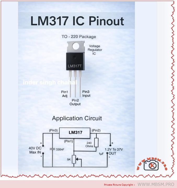
The LM317 is a versatile adjustable linear voltage regulator in a TO‑220 (and SMD) package that delivers a stable output from 1.2 V to 37 V with a maximum input rating of 40 V DC. It’s widely used for bench power supplies, embedded systems, and analog rails where simplicity, low noise, and predictable behavior matter. This article explains pinout and application circuits, common design mistakes, thermal calculations, layout rules, comparisons with alternatives, and practical installation advice.
Pinout and Basic Application
Pin
Label
Function
1
Adj
Adjust input for output set resistor network
2
Out
Regulated output voltage
3
In
Unregulated input voltage (max 40 V DC)
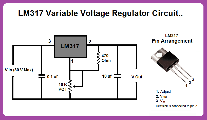
Typical application components:240 Ω resistor between Out and Adj, adjustable resistor (e.g., 5 kΩ) between Adj and ground, 330 nF on Adj for stability in some layouts, and 1 µF on Output for transient suppression.
Standard Application Formula
Output voltage:
where , R1 = 240 Ω, R2 is the adjustable resistor.
Recommended Component Values
Component
Recommended Value
Purpose
R1
240 Ω
Sets reference current
R2
variable 0–5 kΩ
Sets VOUT range
Cadj
330 nF (optional)
Improves transient response and stability
Cout
1 µF low‑ESR
Output decoupling and stability
Cin
10 µF (electrolytic)
Input decoupling and transient handling
Thermal Design and Power Dissipation
Power dissipation:
.
Example: VIN = 24 V, VOUT = 5 V, ILOAD = 0.8 A → . 15.2 W requires a substantial heatsink or a switching alternative.
Practical rule: If W, plan a heatsink or consider a switching regulator. For portable or battery systems, prefer switching converters for efficiency.
Common Mistakes and How to Fix Them
Mistake
Effect
Fix
No input/output decoupling
Oscillation, noise
Add 10 µF on input, 1 µF on output, plus 0.1 µF ceramic close to pins
Long traces to caps
Instability
Place caps within 5 mm of pins; use wide traces
Ignoring thermal dissipation
Overheating, thermal shutdown
Calculate ; add heatsink or switch to buck converter
Wrong capacitor type
Oscillation or poor transient
Use low‑ESR electrolytic or tantalum; pair with ceramic
Using LM317 for large VIN–VOUT
Excessive wasted heat
Use buck converter for large drops or high current
No protection against reverse input
Device failure on faults
Add diode from Out to In and input transient protection
Layout and PCB Best Practices
Place input and output capacitors as close as possible to the regulator pins.
Use wide copper pours for VIN and VOUT to reduce thermal resistance.
Add thermal vias under SMD packages to move heat to inner layers.
Keep adjust resistor network close to Adj pin to minimize noise pickup.
Label test points for VIN, VOUT, and ADJ for easy debugging.
Comparison: LM317 vs. AMS1117 vs. Switching Regulators
Attribute
LM317 (Adjustable LDO)
AMS1117 (Fixed LDO)
Buck Converter (Switching)
Output range
1.2–37 V
Fixed variants (1.2–5 V)
Wide, programmable
Efficiency (large VIN drop)
Low
Low
High
Noise
Low
Moderate
Higher (switching noise)
Thermal stress
High for large VIN–VOUT
High
Low
Complexity
Low
Very low
Higher (inductor, diode, layout)
Best use
Bench supplies, analog rails
Simple fixed rails
High current, battery systems
When to Use LM317
You need an adjustable linear rail with low noise.
VIN is only slightly higher than desired VOUT (small voltage drop).
Current requirements are moderate (typically < 1 A unless heavily heatsinked).
Simplicity and low component count are priorities.
When to Avoid LM317
High current (> 1 A) with large VIN–VOUT difference.
Battery‑powered designs where efficiency is critical.
Very low noise analog front ends that require specialized low‑noise LDOs.
Testing and Validation Checklist
No‑load test: Verify VOUT with no load; confirm VREF ≈ 1.25 V across R1.
Load ramp: Apply increasing load and monitor VOUT and temperature.
Thermal soak: Run full expected load for 30 minutes; measure case and PCB temps.
Transient test: Step load and measure recovery time and overshoot.
Ripple test: Check output ripple with oscilloscope; ensure within system tolerance.
Safety Notes and Notices
Maximum input voltage: Do not exceed 40 V DC on the input pin.
Heat: The package can become hot; use proper insulation and heatsinking.
Polarity: Protect against reverse polarity and input transients.
Capacitor polarity: Observe electrolytic capacitor polarity to avoid explosion.
Practical Design Examples
Scenario
VIN
VOUT
ILOAD
P (W)
Recommendation
Small MCU rail
7 V
5 V
0.2 A
0.4 W
LM317 with small heatsink
Bench 5 V supply
24 V
5 V
0.8 A
15.2 W
Use buck converter or heavy heatsink
Sensor analog rail
12 V
3.3 V
0.1 A
0.87 W
LM317 with decoupling caps
FAQ (Short Answers)
Can LM317 deliver 1 A? Yes, but only with adequate heatsinking and thermal planning.
Do I need the 240 Ω resistor? Yes; it sets the reference current and stabilizes the regulator.
How to reduce noise? Use proper decoupling, a 0.1 µF ceramic near pins, and a low‑ESR output cap.
Focus Keyphrase
LM317 adjustable voltage regulator TO‑220 pinout 1.2–37V 40V IN application circuit thermal design decoupling layout mistakes
SEO Title
Mbsmpro.com, LM317 Voltage Regulator, TO‑220, 1.2–37V, 40V IN, Pinout, Application Circuit, Thermal Design
Meta Description
Complete LM317 guide: pinout, application circuit, component values, thermal calculations, PCB layout tips, common mistakes, and comparisons with AMS1117 and switching regulators.
LM317 is a flexible adjustable linear regulator delivering 1.2 V to 37 V from a 40 V max input. This guide covers pinout, recommended component values, thermal calculations, layout best practices, common mistakes, and when to choose switching alternatives for efficiency and high current.
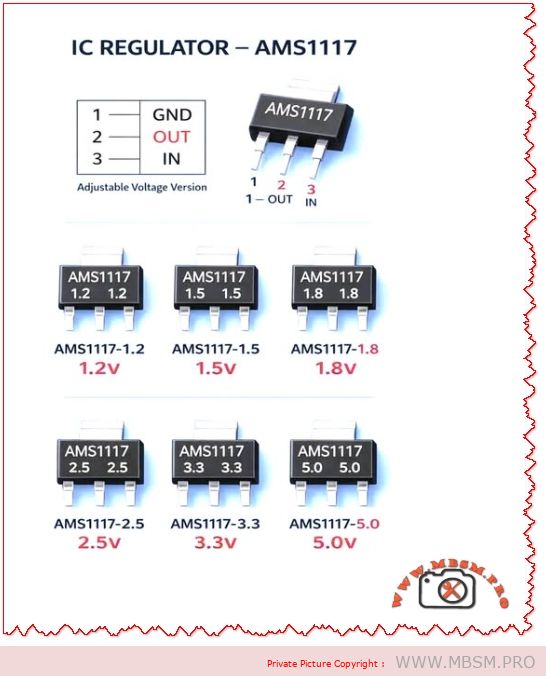
AMS1117 Voltage Regulator: Common Mistakes, Practical Guide, and Engineering Best Practices
Overview The AMS1117 family of linear voltage regulators (fixed and adjustable versions) is ubiquitous in electronics projects, embedded systems, and power-supply rails. Despite its popularity, technicians and hobbyists repeatedly make the same installation and design mistakes that cause overheating, instability, and premature failure. This article explains those common mistakes, gives engineering‑grade corrections, compares AMS1117 variants with alternatives, and supplies practical tables, values, and installation checklists you can use in a WordPress technical post.
Why AMS1117 Is Widely Used
Simple three‑pin package (GND, OUT, IN) makes board layout straightforward.
Thermal plan: Heatsink area, copper pour, and airflow if W.
Layout: Short traces, wide copper, thermal vias under package for SMD variants.
Protection: Input TVS, series fuse, reverse‑polarity protection.
Testing: Thermal imaging under full load; measure output ripple and transient response.
Thermal Calculation Example
Given: VIN = 12 V, VOUT = 5 V, ILOAD = 0.8 A
Dissipation:
Implication: 5.6 W requires substantial heatsinking; AMS1117 in a TO‑220 or SOT‑223 without heatsink will overheat. Consider switching regulator.
Comparison Table: AMS1117 vs. Common Alternatives
Attribute
AMS1117 (Linear)
LM2596 (Buck)
LDO Modern (e.g., MIC5219)
Efficiency at 5 V out from 12 V in
~42%
~85–95%
~42–60%
Typical max current
~1 A (thermally limited)
3 A (switching)
500 mA–1 A
Output noise
Low‑mid
Higher switching noise
Low
Board complexity
Low
Higher (inductor, diode, caps)
Low
Thermal stress
High for large VIN–VOUT
Low
Moderate
Best use case
Small loads, simple designs
High current, large step‑down
Low‑noise low‑current rails
When to Choose AMS1117 (Use Cases)
Low‑power microcontroller rails (e.g., 3.3 V at < 300 mA).
Simple sensor boards where VIN is close to VOUT (small voltage drop).
Prototyping and low‑volume products where cost and simplicity matter.
When to Avoid AMS1117 (Alternatives)
High current (>1 A) or large VIN–VOUT difference — use a buck converter.
Battery‑powered designs where efficiency is critical — use switching regulator.
Very low noise analog rails — choose a precision LDO with low noise spec.
Layout and PCB Best Practices
Place caps within 2–5 mm of regulator pins.
Use wide input and output traces (or pour copper) to reduce voltage drop and improve heat spreading.
Add thermal vias under SMD packages to move heat to inner or bottom copper.
Keep sensitive analog traces away from the regulator’s hot copper and switching nodes (if present).
Label polarity clearly and include test points for VIN, VOUT, and GND.
Testing and Validation Steps
No‑load test: Verify VOUT with no load; check for oscillation.
Step‑load test: Apply sudden load changes and measure transient response.
Thermal test: Run at maximum expected load for 30 minutes; measure case and PCB temps.
Ripple test: Measure output ripple with oscilloscope; ensure within tolerance for your circuit.
Fault test: Simulate short‑circuit and overvoltage to confirm protection behavior.
Common Failure Modes and Troubleshooting
Symptom: Output drops under load → Check thermal shutdown, insufficient input voltage, or current limit.
Symptom: Output noisy or oscillating → Check output capacitor ESR and placement.
Symptom: Device hot to touch → Check power dissipation calculation and add heatsink or switch to buck converter.
Symptom: No output → Check input presence, reverse polarity protection, and solder joints.
Engineering Notes and Practical Tips
Combine capacitors: a 0.1 µF ceramic in parallel with a 10 µF electrolytic gives best high‑ and low‑frequency performance.
Derate current: assume 70–80% of the absolute max in real designs unless thermal path is proven.
Use thermal simulation or simple hand calculations to size copper pour and heatsink.
Document expected VIN range and include transient protection if VIN can spike (e.g., automotive or industrial environments).
Focus Keyphrase
AMS1117 common mistakes thermal design decoupling capacitor layout oscillation protection buck alternative 1.2V 1.8V 3.3V 5V regulator
SEO Title
Mbsmpro.com, AMS1117 Voltage Regulator, Common Mistakes, Thermal Design, 1.2V–5.0V, Decoupling, Layout, Alternatives
Meta Description
Avoid overheating and instability with AMS1117 regulators. Learn the most common mistakes, thermal calculations, capacitor recommendations, PCB layout tips, and when to choose a buck converter instead.
AMS1117, Voltage Regulator, LDO, Decoupling, Thermal Design, PCB Layout, Buck Converter, 3.3V, 5V, Mbsmgroup, Mbsm.pro, mbsmpro.com, mbsm, Electronics, Power Supply
Excerpt (first 55 words)
AMS1117 linear regulators are simple and cheap, but common mistakes—missing decoupling, poor thermal planning, and long traces—cause instability and overheating. This guide explains capacitor choices, power dissipation math, PCB layout rules, testing steps, and when to switch to a buck converter for efficiency and reliability.
AMS1117 Voltage Regulator Pinout and Versions: Complete Guide for Electronics Projects
The AMS1117 family is one of the most widely used linear regulators for stepping down DC voltages in embedded and DIY electronics projects. Its simple three‑pin layout and multiple fixed output versions make it an excellent choice for powering microcontrollers, sensors, and communication modules.
AMS1117 overview
The AMS1117 is a low‑dropout (LDO) linear voltage regulator capable of delivering up to 1 A of continuous current, depending on heat dissipation and PCB design.
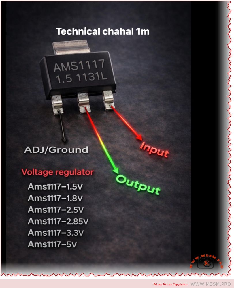
It is available as fixed‑output regulators (1.5 V, 1.8 V, 2.5 V, 2.85 V, 3.3 V, 5 V and others) and as an adjustable version that can be set from about 1.25 V to 12 V using external resistors.
Pinout: input, output, and ground/ADJ
In the common SOT‑223 package, the pins from left to right (front view, text facing you) are ADJ/GND, OUTPUT, and INPUT.
For fixed versions (such as AMS1117‑3.3 or AMS1117‑5.0), the first pin is tied to ground, while for the adjustable version it is used as the ADJ pin to set the output voltage with a resistor divider.
Fixed output AMS1117 variants
The table below summarizes popular fixed‑voltage versions and typical use cases.
AMS1117 version
Nominal output
Typical application example
AMS1117‑1.5
1.5 V
Low‑voltage ASICs, reference rails
AMS1117‑1.8
1.8 V
ARM cores, SDRAM, logic ICs
AMS1117‑2.5
2.5 V
Older logic families, ADC/DAC rails
AMS1117‑2.85
2.85 V
Mobile RF, modem chipsets
AMS1117‑3.3
3.3 V
MCUs, sensors, 3.3 V logic from 5 V sources
AMS1117‑5.0
5.0 V
Regulating from 7–12 V to 5 V logic or USB lines
Electrical characteristics and design tips
The typical input range for AMS1117 regulators is up to 12–15 V, with a dropout voltage around 1.1–1.3 V at 1 A, meaning the input must be at least about 1.3 V higher than the desired output.
For stable operation, manufacturers recommend small bypass capacitors at both input and output (for example 10 µF electrolytic or tantalum), which help reduce noise and improve transient response in digital circuits.
Typical applications in embedded systems
AMS1117 regulators are frequently used to derive 3.3 V from 5 V USB or 9–12 V adapter inputs in Arduino‑style development boards and sensor modules.
Thanks to built‑in thermal shutdown and short‑circuit protection in many implementations, these regulators offer a robust solution for compact PCBs, IoT nodes, and hobby electronics where space and simplicity are critical.
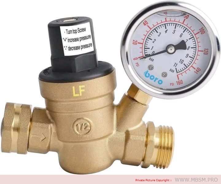
A water pressure regulator is a device used in water systems to reduce and adjust the pressure of water coming from the source (such as a public water supply) to a safe and constant level suitable for domestic or industrial use.
Importance of a Water Pressure Regulator:
Protecting Pipes and Appliances:
Prevents damage caused by high water pressure that may affect plumbing systems and appliances such as washing machines and water heaters.
Reducing Water Consumption:
Reduces excessive water flow, helping to conserve water and lower bills.
Improving Performance:
Ensures a consistent water flow, enhancing the efficiency of appliances and providing a better user experience.
Extending System Lifespan:
Prevents excessive pressure that may cause leaks or damage to pipes and fittings.
Components of a Water Pressure Regulator:
Pressure-Reducing Valve:
The part responsible for reducing water pressure to the desired level.
Internal Spring:
Controls the pressure and ensures it remains stable at the set value.
Pressure Gauge:
Displays the current pressure level (available in some models).
Inlet and Outlet:
Connections that link the regulator to the water source and the pipes leading to the point of use.
Types of Water Pressure Regulators:
Fixed Regulator:
Reduces pressure to a specific, non-adjustable level.
Adjustable Regulator:
Allows the user to adjust the pressure according to their needs.
Integrated Water Pressure Regulator:
Includes additional features such as a pressure gauge or an internal filter.
How to Choose the Right Water Pressure Regulator:
Water Pressure at the Source:
Determine the incoming water pressure to select a regulator that suits the current pressure.
Type of Use:
Choose a regulator suitable for domestic or industrial use.
Construction Materials:
Ensure the regulator is made of corrosion-resistant materials such as brass or stainless steel.
Pipe Size:
Make sure the connection size is compatible with your water pipes.
Advantages of Using a Water Pressure Regulator:
Reducing the Risk of Bursts:
Prevents pipe damage due to sudden high pressure.
Maintaining Stable Water Flow:
Provides consistent water pressure for appliances and daily use.
Saving on Bills:
Helps reduce water consumption, lowering costs.
Reducing Noise:
Minimizes noise caused by high-speed water flow in pipes.
Maintenance and Common Issues:
Clogged Filter:
Accumulation of sediment and debris can cause blockages. Clean the filter regularly.
Damaged Internal Spring:
The spring may lose its elasticity over time, affecting the regulator’s performance. Replace it if necessary.
Water Leaks:
Ensure connections are tightly sealed and replace damaged rubber seals.
Unstable Pressure:
This may be due to a damaged valve or spring. Inspect the regulator and replace faulty parts.
Maintenance Tips:
Regularly inspect the regulator to ensure it is functioning efficiently.
Clean the internal filter every 6 months or as needed.
Check for leaks in the connections.
Replace the regulator if it is significantly damaged or unable to maintain pressure.
Conclusion:
A water pressure regulator is an essential device for protecting water systems and household appliances from high pressure. By choosing the right type and performing regular maintenance, you can ensure a safe and consistent water flow while saving on costs and extending the lifespan of your systems.
Mbsm.pro, 3A Adjustable voltage regulator circuit from 12 v to 5 v DC
Category: electronique
written by rober us | 8 January 2026
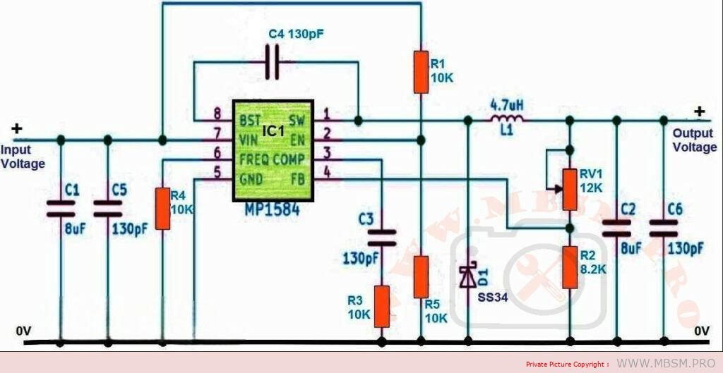
1. Switching Regulator with Adjustable Output:
High Efficiency: Ideal for high-current applications due to their efficient power conversion, reducing heat generation.
Wide Input Voltage Range: Often handle a broad range of input voltages.
Compact Size: Typically smaller than linear regulators with similar current ratings.
Adjustability: Some switching regulator ICs offer built-in adjustable output voltage control.
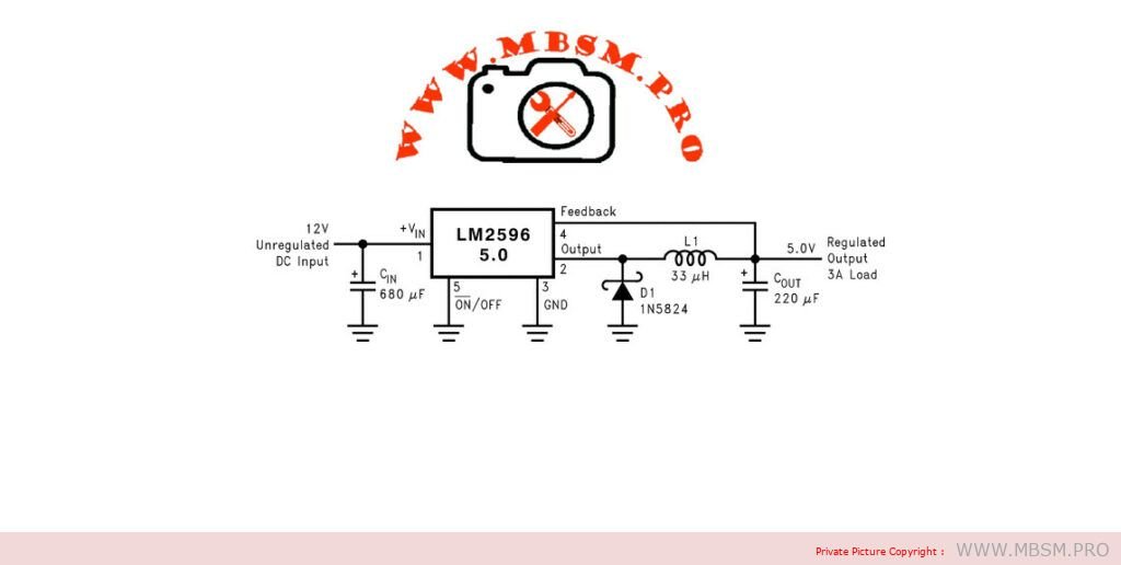
Examples of Switching Regulator ICs with Adjustable Output:
LM2596
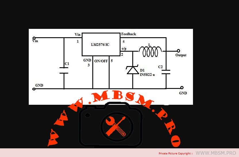
LM2576
MP1584
2. Linear Regulator with External Pass Transistor and Adjustable Control:
Simpler Design: Uses a linear regulator IC, an external power transistor, and adjustable control components.
Less Efficient: Dissipates excess power as heat, requiring adequate heatsinking.
Components:
Linear Regulator IC: Provides basic voltage regulation, but with a limited current output.
Power Transistor: Handles high current flow.
Heatsink: Dissipates heat from the transistor.
Adjustable Resistors: Allow for fine-tuning of the output voltage.
Additional Considerations:
Heat Dissipation: Both switching and linear regulators with high currents generate heat. Provide sufficient heatsinking.
Input Voltage Range: Ensure the regulator can handle your input voltage range.
Desired Adjustment Range: Choose a regulator that offers the level of output voltage adjustability you need.
Safety Features: Consider regulators with overcurrent protection, thermal protection, and short-circuit protection.
Specific Circuit Design and Component Selection:
Depend on your exact current, voltage, and adjustability requirements.
Consult datasheets and application notes for the chosen regulator ICs for detailed guidance.
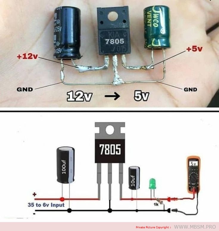
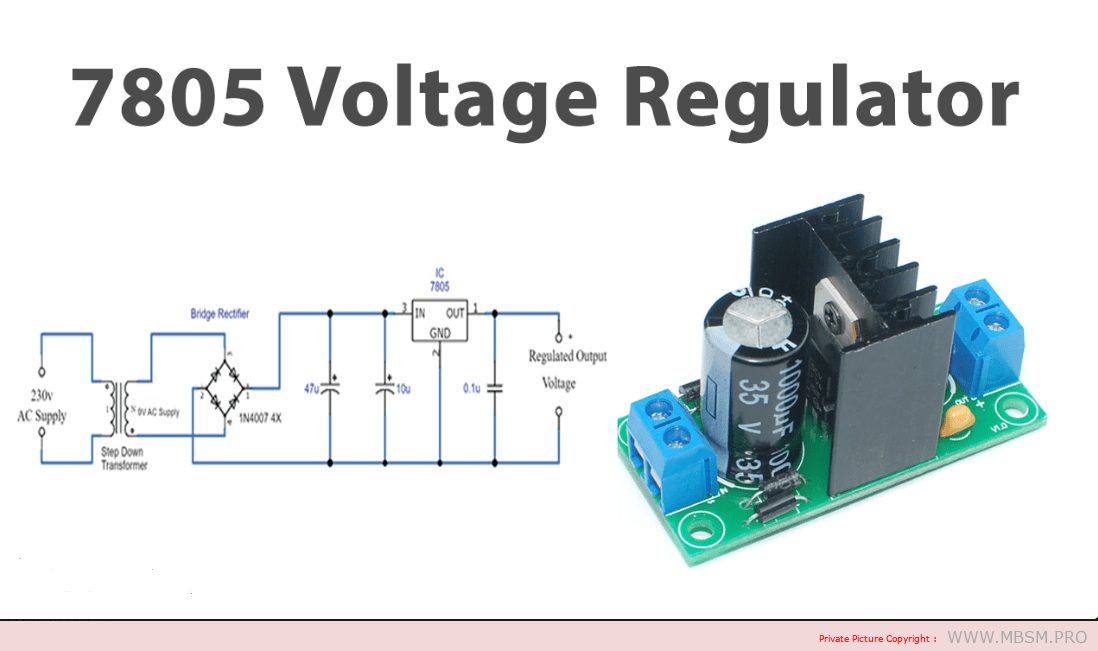
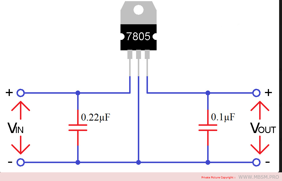
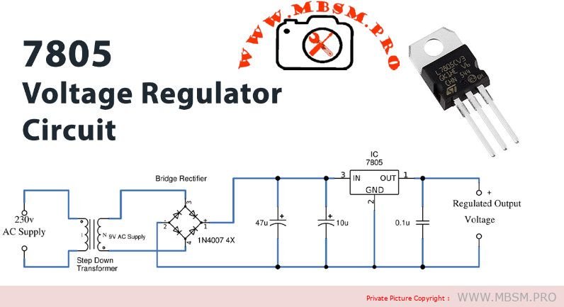
7805 Voltage Regulator IC: This three-pin integrated circuit (IC) is the heart of the circuit. It regulates the voltage to a constant 5 volts at its output, even if the input voltage varies.
Input Capacitor (Cin): This capacitor helps to filter out any unwanted ripple or noise from the input voltage, providing a smoother input to the regulator.
Output Capacitor (Cout): This capacitor helps to smooth out any voltage fluctuations at the output, ensuring a stable 5 volts for the connected circuitry.
Heatsink (optional): If the regulator is expected to handle significant current, a heatsink may be necessary to dissipate heat and prevent overheating.
Connections:
Input Pin (VIN): Connect this pin to the unregulated DC input voltage source.
Ground Pin (GND): Connect this pin to the ground of both the input and output circuits.
Output Pin (VOUT): Connect this pin to the load or circuitry that requires a regulated 5 volts.
Key Points:
Input Voltage Range: The 7805 can handle input voltages ranging from 7 to 35 volts.
Output Voltage: The fixed output voltage is 5 volts.
Maximum Output Current: The 7805 can provide up to 1 amp of output current.
Heat Management: If using high input voltages or driving high currents, a heatsink is essential for proper heat dissipation.
Common Applications:
Powering microcontrollers, sensors, and other low-power electronics
Providing a stable voltage reference for circuits
Creating a 5-volt power supply for DIY projects
Used in various electronic devices like computers, audio equipment, and industrial machinery
Input Amperage:
Not fixed: The 7805’s input amperage is not a fixed value, but rather depends on the demands of the connected load.
Regulates voltage, not current: The regulator’s primary function is to maintain a constant 5-volt output, but it adjusts the input current as needed to achieve this.
Simplified Equation: Input Amperage ≈ Output Amperage ≈ Load Current (approximately, as there’s some internal power consumption)
Output Amperage:
Maximum Output Current: The 7805 can provide a maximum output current of 1 amp.
Heat Considerations: If the load requires close to 1 amp, a heatsink is crucial to prevent overheating and potential damage.
Key Points:
Input Current Matches Load Demand: The 7805’s input current will automatically adjust to match the current required by the load.
Maximum Output Current 1 Amp: The regulator can deliver up to 1 amp of current at its output.
Heatsink for Higher Currents: If using the regulator near its maximum output current, a heatsink is essential for proper heat dissipation.
Additional Considerations:
Efficiency: The 7805 is a linear regulator, so it does dissipate some power as heat, especially at higher input voltages and currents.
Power Dissipation: Consider the power dissipation (input voltage – output voltage) * output current to determine if a heatsink is necessary.
Alternatives: For higher efficiency or higher output currents, consider switching regulators.
Mbsm.pro , LM317 ,Voltage Regulator Pin Outs, Simple test, voltage regulators ics , Voltage regulator
Category: Développement,electronique
written by www.mbsm.pro | 8 January 2026
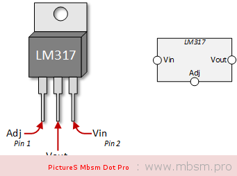
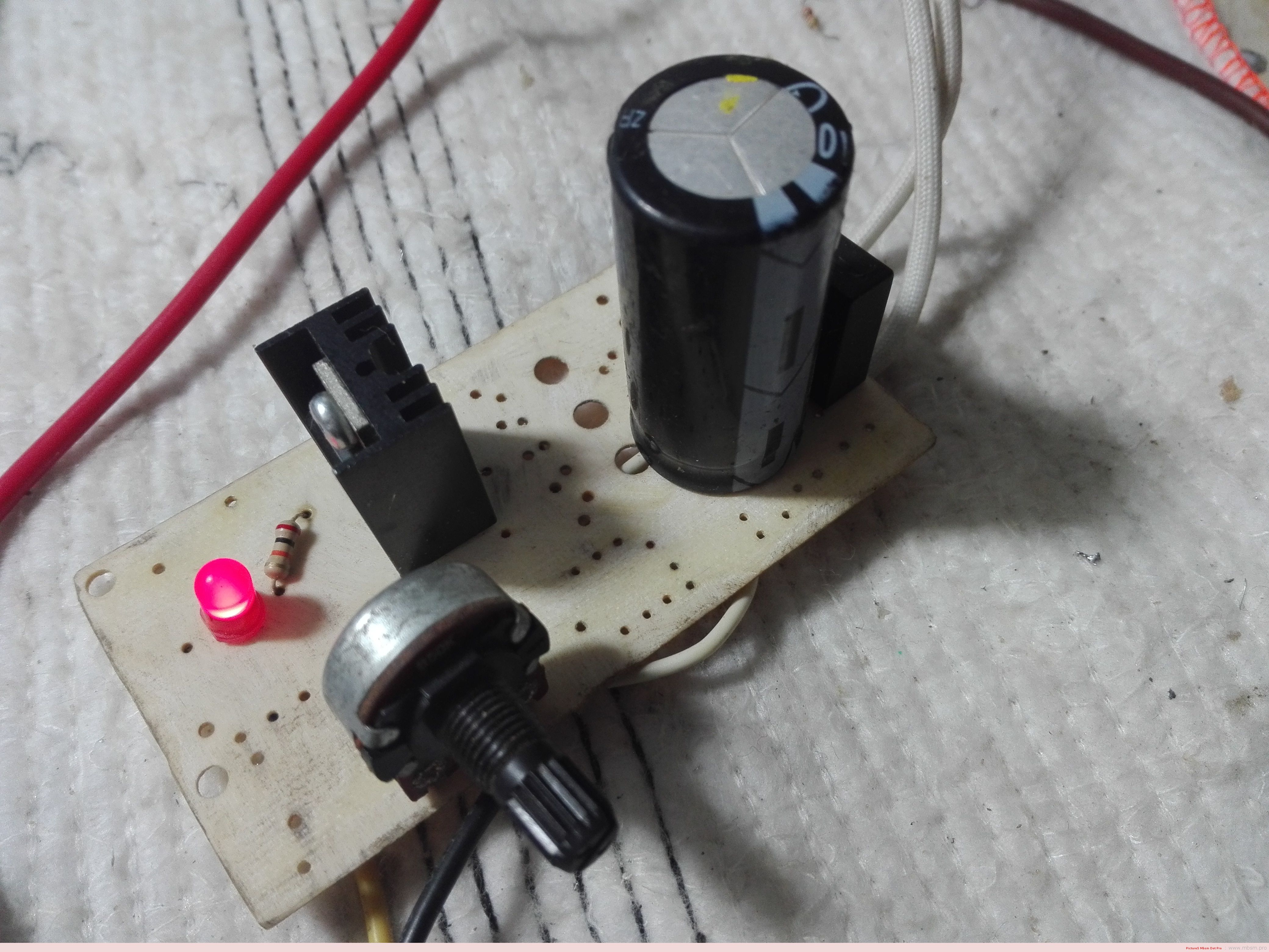
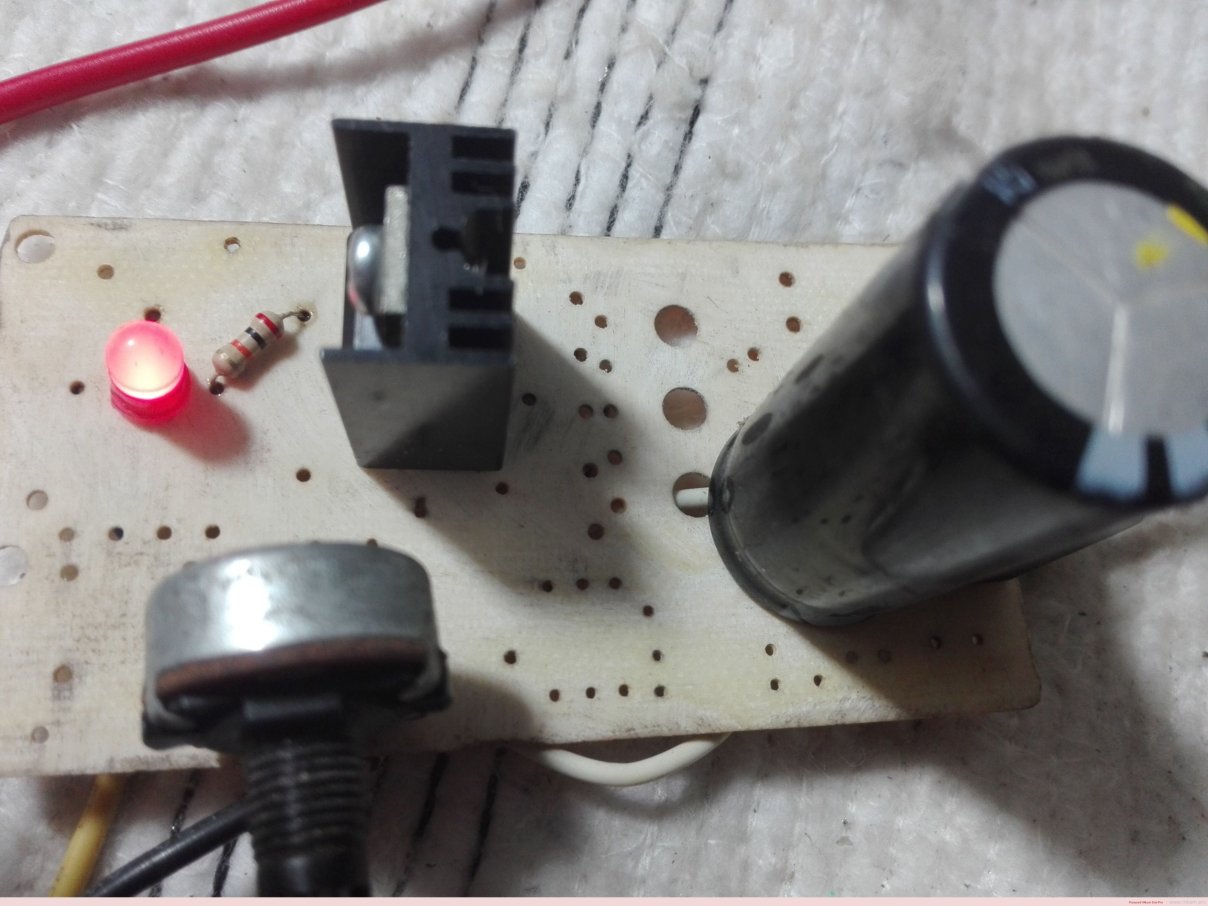
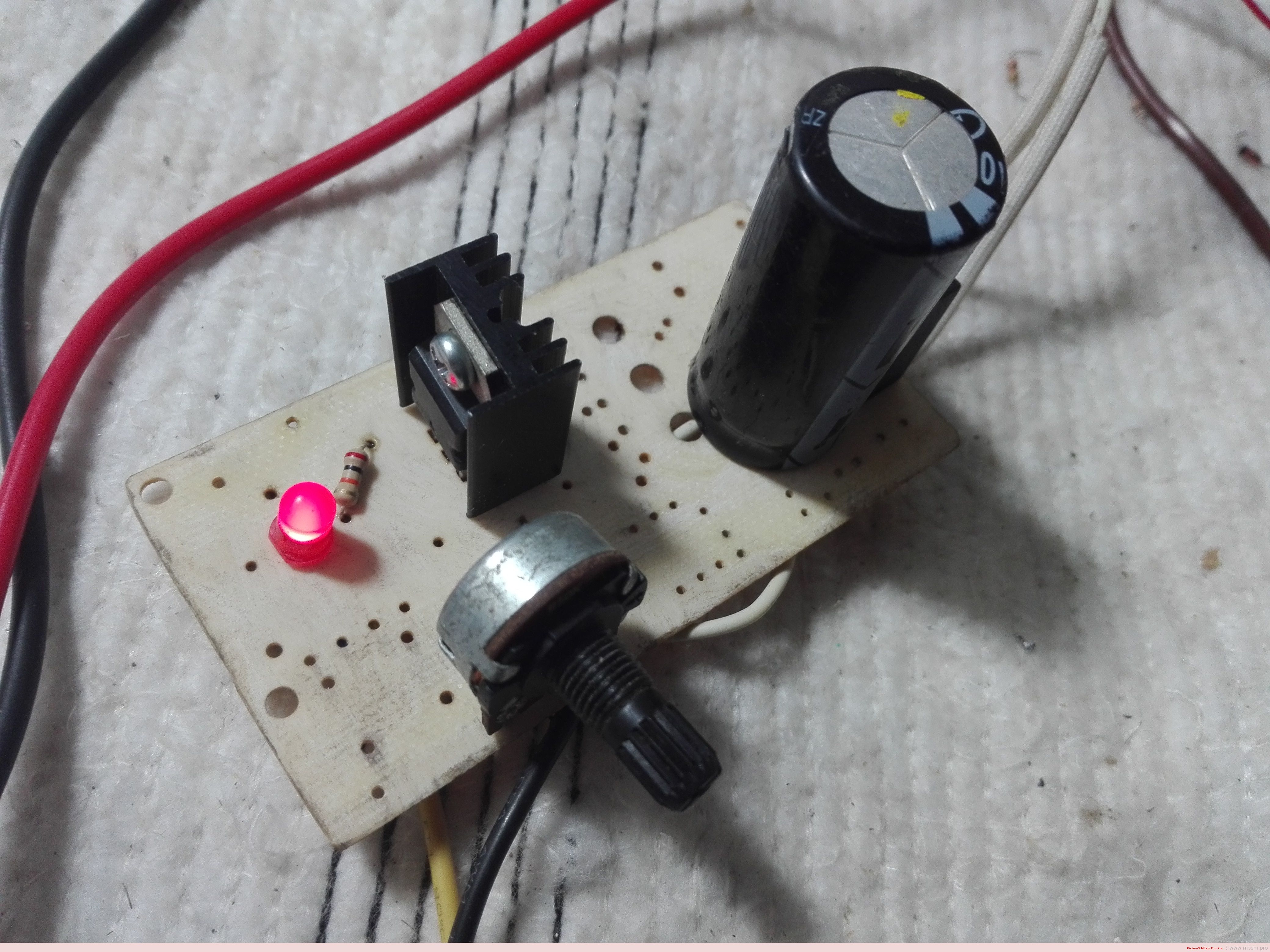
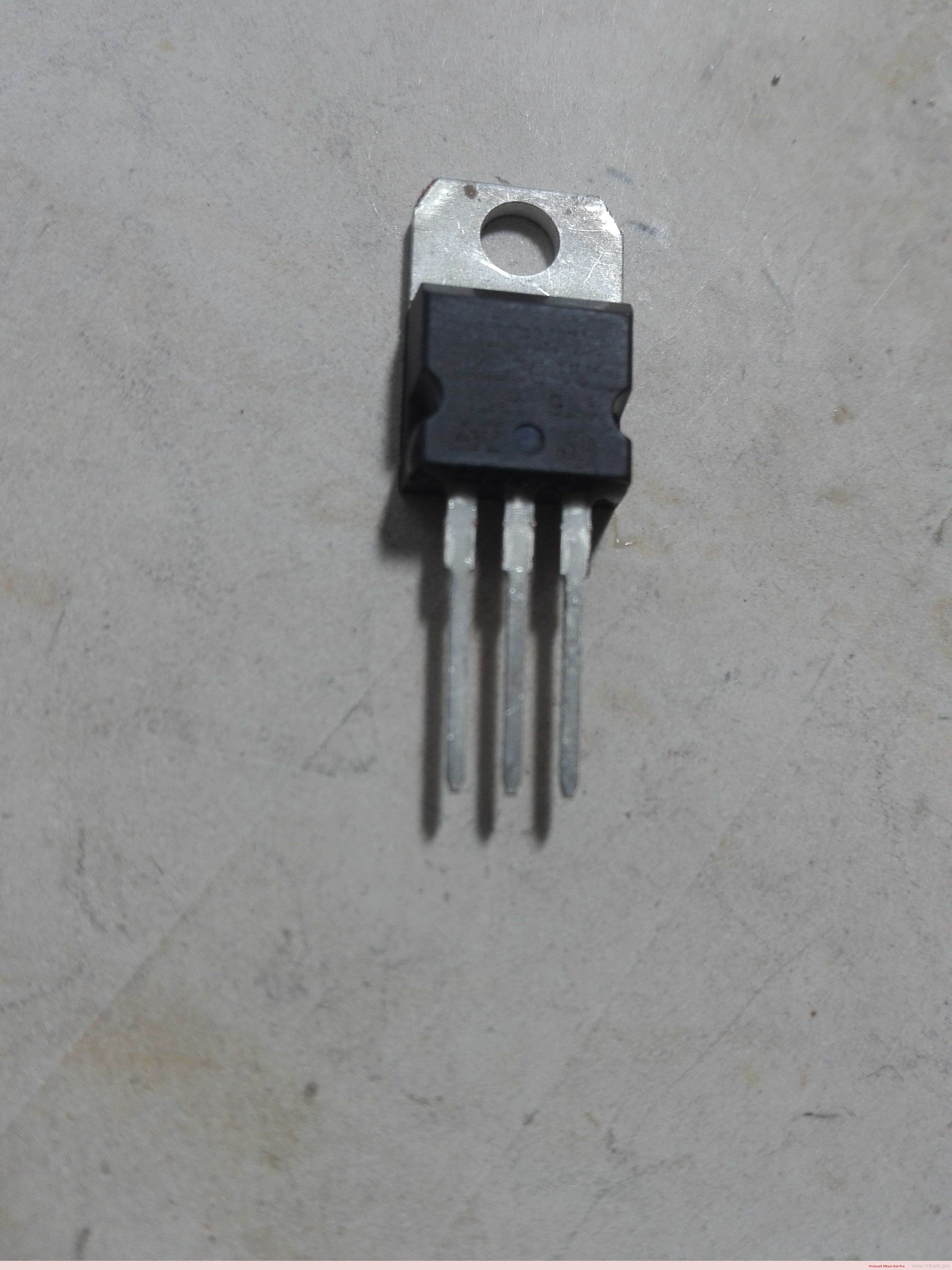
The LM317 is most commonly found in a TO220 package. It only has three pins and we will be using all of them in this tutorial.
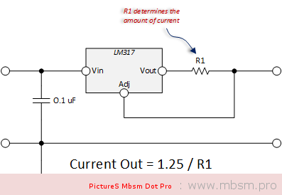
The LM317 Voltage Regulator for Current Control
The use of an LM317 as a constant current source comes right from the data sheet. The schematic below shows how to configure the LM317 as a current regulator. It is the value of R1 that you will be concerned about and that value is determined by the type of LED you are using.
The math is really simple. The factor of 1.25 also comes from the data sheet.
Let’s walk through an example:
Lets say you wanted to control to 300 mA. You would determine that your optimum resistor is: R1 = 1.25 / 0.300 = 4.17 Ohms
Next you’re going to poke around in your box of resistors to see what you’ve got. You probably won’t find that 4.17 Ohm resistor, so you will want to try something close. I had a 4.7 Ohm resistor.
Now you’re going to want to apply the formula to see what that gets you. Current Out = 1.25 / 4.7 = 266 mA.
Finally, we need to do a sanity check of the power rating of the resistor. Here we will use I2 x R to get the power dissipated by the resistor. Power Dissipated by Resistor = 0.2662 x 4.7 = 0.332 Watts (a half watt resistor will do the trick)
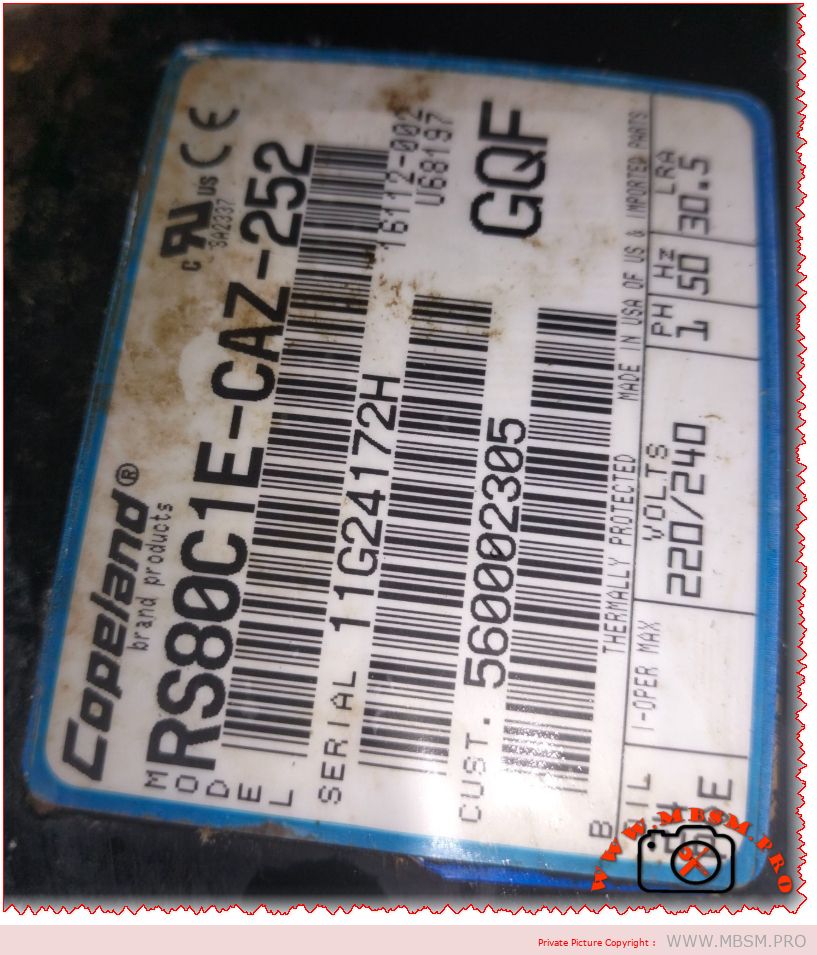
The Copeland RS80C1E-CAZ-252 represents a specialized hermetic reciprocating compressor engineered for low-temperature refrigeration applications where reliability meets efficiency. This single-phase unit operates on R134a refrigerant and delivers consistent performance in demanding freezing environments ranging from -30°C to -10°C evaporating temperatures.
Technical Overview and Application Domain
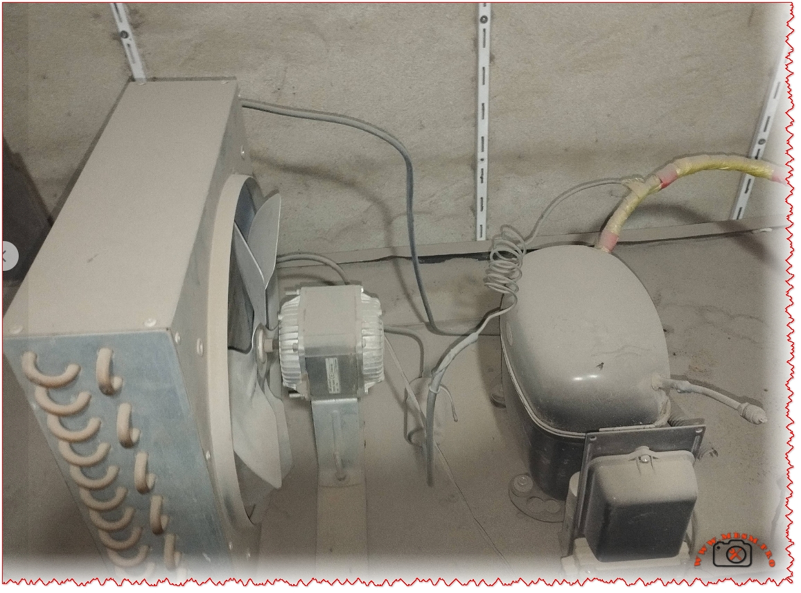
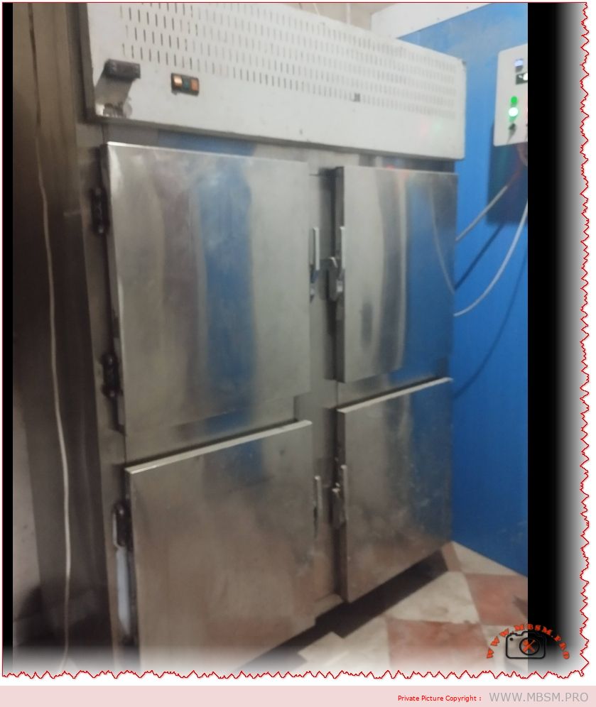
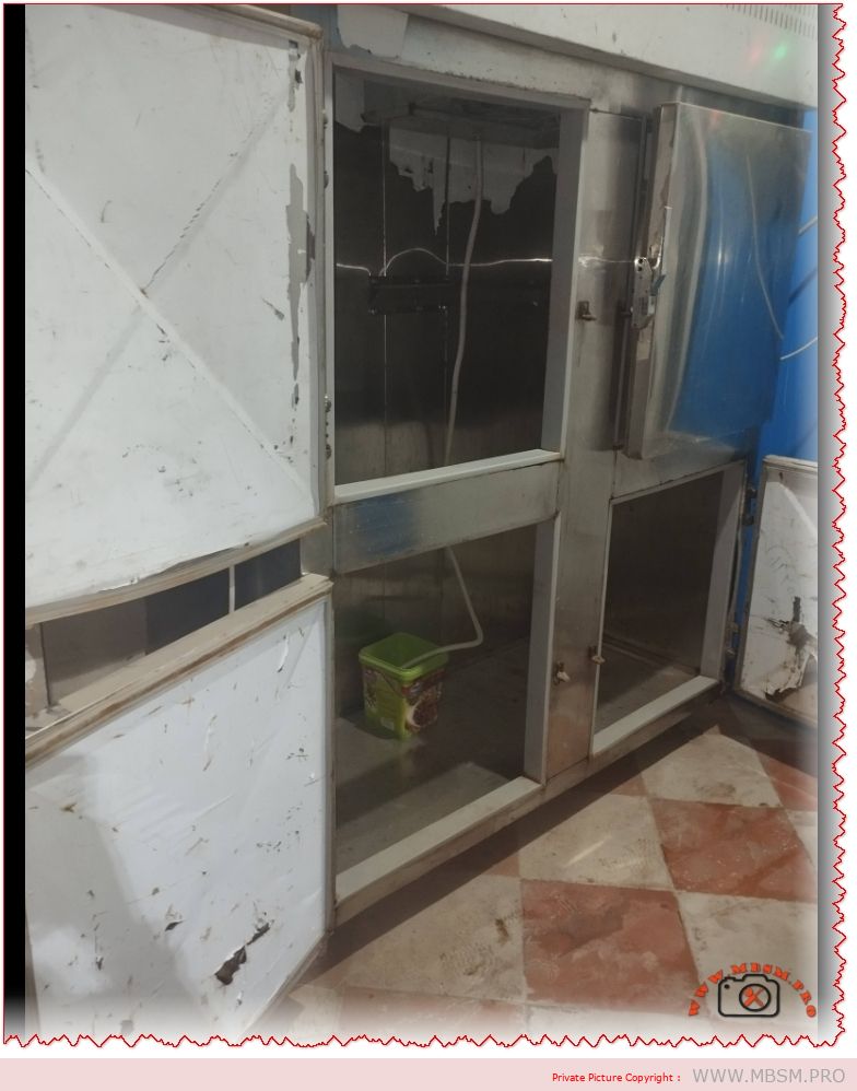
The RS80C1E-CAZ-252 belongs to Copeland’s proven RS series of hermetic reciprocating compressors, designed specifically for commercial refrigeration applications requiring low back pressure operation. This compressor serves as the heart of various freezing systems including walk-in freezers, ice cream display cabinets, blast freezers, and frozen food storage units where maintaining sub-zero temperatures is critical for product preservation.
Operating at 220-240V single-phase 50Hz power supply, this unit draws approximately 5 amperes during normal operation, making it suitable for standard commercial electrical systems. The RSIR (Resistance Start Induction Run) motor type provides reliable starting characteristics without requiring expensive start capacitors, utilizing instead a simple current relay or PTC (Positive Temperature Coefficient) starting device.
Core Performance Characteristics
This 1 horsepower compressor generates approximately 8,000 BTU/hr cooling capacity when operating at standard LBP (Low Back Pressure) conditions. The displacement volume typically measures around 10.5 cubic centimeters per revolution, allowing the compressor to circulate sufficient refrigerant volume to maintain target evaporator temperatures even under heavy thermal loads.
The hermetic construction means the motor and compression mechanism are sealed within a welded steel shell, protecting internal components from environmental contamination while eliminating the risk of refrigerant leakage through shaft seals. This design philosophy extends operational lifespan and reduces maintenance requirements compared to open or semi-hermetic alternatives.
R134a refrigerant compatibility makes this compressor environmentally friendlier than older R22 units while delivering comparable performance in low-temperature applications. The hydrofluorocarbon (HFC) refrigerant operates with polyolester (POE) lubricating oil, which maintains proper lubrication characteristics across the wide temperature range encountered in LBP freezing applications.
Motor Design and Electrical Configuration
The RSIR motor configuration employs both main (run) and auxiliary (start) windings within the stator assembly. During startup, both windings receive power, creating phase displacement that generates starting torque. Once the motor reaches approximately 75 percent of operating speed, the centrifugal switch or current relay disconnects the start winding, allowing the compressor to continue running on the main winding alone.
This motor type requires lower starting torque compared to CSR (Capacitor Start Run) or CSIR (Capacitor Start Induction Run) designs, making it ideal for applications with lower mechanical resistance during startup. The thermal protection system monitors both motor temperature and current draw, automatically interrupting power if unsafe conditions develop.
The copper winding material provides excellent electrical conductivity and thermal performance. Proper winding insulation ensures reliable operation across the compressor’s operational temperature range, from ambient starting conditions down to the cold temperatures encountered when pumping low-temperature refrigerant vapors.
Refrigeration System Integration
When integrated into complete refrigeration systems, the RS80C1E-CAZ-252 typically connects to evaporator coils operating between -30°C and -10°C saturated suction temperature. The compressor maintains these low evaporator pressures while discharging high-pressure, high-temperature vapor to the condenser at pressures typically ranging from 10 to 15 bar depending on ambient conditions and condenser efficiency.
Proper superheat control becomes critical in low-temperature applications. Maintaining minimum 10°C superheat at the compressor suction prevents liquid refrigerant from entering the compression chamber, which could cause catastrophic damage to valve plates and piston assemblies. Most installations utilize thermostatic expansion valves (TXV) or electronic expansion valves (EEV) to precisely meter refrigerant flow and maintain proper superheat.
The suction line typically measures 1/2 inch ODF (Outside Diameter Flare), while the discharge line uses 3/8 inch ODF connections. Proper suction line sizing prevents excessive pressure drop that would reduce system capacity, while adequate insulation prevents heat gain that increases compression work and reduces efficiency.
Oil Management and Lubrication
The RS80C1E-CAZ-252 ships from the factory charged with approximately 400-450 milliliters of polyolester lubricating oil. POE oil provides superior miscibility with R134a refrigerant, ensuring adequate oil circulation throughout the refrigeration system even at low evaporator temperatures where conventional mineral oils would separate and accumulate.
In low-temperature applications, proper oil return becomes paramount. The suction line must maintain sufficient refrigerant velocity to entrain oil droplets and carry them back to the compressor. Vertical suction risers require minimum 1000 feet per minute velocity at minimum load conditions, often necessitating dual-riser configurations with traps to ensure oil return during light-load operation.
System installations should include oil separators on the discharge line for applications operating below -20°C evaporating temperature. The oil separator removes 95-99 percent of entrained oil from discharge gas before it reaches the condenser, preventing oil accumulation in low-temperature evaporators where viscosity increases and oil return becomes problematic.
Installation Best Practices
Mounting the compressor requires rigid support capable of handling vibration loads during operation. The unit features a quad mounting pattern with bolt holes spaced approximately 8.0 inches by 4.8 inches, standard for this compressor frame size. Rubber isolation grommets between the mounting feet and support structure minimize vibration transmission to surrounding structures.
Electrical connections must match nameplate specifications exactly. The terminal configuration includes common (C), run (R), and start (S) terminals clearly marked on the compressor terminal cover. Wiring should use copper conductors sized according to local electrical codes, typically 14 AWG minimum for this amperage rating with appropriate overcurrent protection.
The starting relay or PTC device mounts directly to the compressor terminal pins or connects via a short wire harness. Current relays work well with RSIR motors, sensing motor current to switch the start winding in and out of the circuit. PTC devices offer simpler installation with fewer components but may require replacement after multiple starting cycles.
Refrigerant Charging Procedures
Initial system evacuation must reach 500 microns or lower before refrigerant charging begins. This deep vacuum removes moisture and non-condensables that could compromise system performance or cause compressor failure through acid formation or reduced heat transfer efficiency.
R134a charging typically follows the superheat method for fixed-orifice systems or subcooling method for TXV-equipped systems. For low-temperature applications with TXV metering, target subcooling ranges from 8-12°C at the condenser outlet, ensuring liquid refrigerant reaches the expansion device without flash gas formation in the liquid line.
Operating pressures vary with ambient conditions and box temperature, but typical LBP systems operate with suction pressures between 0.5-2.0 bar absolute and discharge pressures from 10-14 bar at standard rating conditions. Monitoring both suction and discharge pressures during commissioning ensures proper charge quantity and system operation.
Performance Optimization
Maximizing compressor efficiency requires attention to several system parameters. Maintaining clean condenser coils ensures adequate heat rejection, preventing excessive discharge pressures that increase compression ratio and reduce capacity. Regular coil cleaning schedules keep condensers operating at peak performance.
Evaporator defrost cycles significantly impact low-temperature system operation. Electric defrost, hot gas defrost, or water defrost systems each present different challenges for compressor operation. Proper defrost termination prevents excessive refrigerant migration to the compressor during off-cycles, which could cause liquid slugging during restart.
Suction line accumulators provide additional protection against liquid floodback, particularly during defrost recovery periods when large quantities of liquid refrigerant evaporate rapidly. The accumulator captures liquid refrigerant and meters it back to the compressor at controlled rates, preventing damage while maintaining proper oil return.
Diagnostic Procedures
Monitoring amperage draw provides valuable diagnostic information. Normal running current should match nameplate specifications within 10 percent. Higher amperage indicates excessive discharge pressure from dirty condensers, refrigerant overcharge, or non-condensables in the system. Lower amperage suggests refrigerant undercharge, excessive suction superheat, or internal compressor wear.
Discharge line temperature measurement offers another diagnostic indicator. Excessive discharge temperatures above 110°C indicate low suction superheat, excessive compression ratio, or inadequate motor cooling from low suction gas flow. Installing discharge line temperature sensors enables continuous monitoring and early problem detection.
Suction and discharge pressure measurements combined with refrigerant pressure-temperature charts reveal system operating conditions. Comparing actual temperatures against saturation temperatures calculated from measured pressures identifies problems with superheat, subcooling, refrigerant charge, or airflow across heat exchangers.
Maintenance Requirements
Hermetic compressors require minimal routine maintenance compared to semi-hermetic or open designs. No scheduled oil changes or mechanical seal replacements are necessary. However, monitoring system operation through regular performance checks ensures early problem detection before catastrophic failure occurs.
Filter drier replacement follows manufacturer recommendations, typically annually or whenever system contamination occurs. Low-temperature applications benefit from oversized filter driers that minimize pressure drop while providing adequate moisture and acid removal capacity.
Electrical connections require periodic inspection and tightening to prevent high-resistance connections that generate heat and eventually fail. Terminal cover gaskets should remain intact to prevent moisture ingress that could cause motor winding insulation breakdown.
Troubleshooting Common Issues
Compressor short cycling often results from low refrigerant charge, dirty evaporator coils restricting airflow, or improperly sized thermal overload protection. Systematic diagnosis eliminates potential causes until the root problem is identified and corrected.
Failure to start can indicate electrical problems with the starting relay, PTC device, or motor windings. Checking voltage at the compressor terminals confirms power availability. Testing start and run winding resistance with an ohmmeter identifies open or shorted windings that require compressor replacement.
Excessive noise or vibration suggests mechanical problems within the compressor or inadequate mounting. Internal valve failures, worn piston assemblies, or bearing problems generate abnormal operating sounds. Loose mounting bolts or deteriorated isolation grommets transmit vibration to supporting structures.
Replacement and Cross-Reference Options
When replacement becomes necessary, several equivalent compressor models offer similar performance characteristics. Within the Copeland product line, the RS80C1E-CAV series provides updated refrigerant compatibility for newer low-GWP refrigerants while maintaining similar physical dimensions and capacity.
Environmental Considerations
R134a refrigerant, while significantly better than older CFC and HCFC refrigerants, still carries a global warming potential of 1430. Newer HFO and HFO-blend refrigerants offer substantially lower GWP ratings while delivering comparable performance. Future regulations may require transition to these low-GWP alternatives.
Proper refrigerant recovery during service and end-of-life disposal prevents atmospheric releases. Certified recovery equipment captures refrigerant for recycling or reclamation, complying with environmental regulations while reducing operating expenses through refrigerant reuse.
Energy efficiency impacts environmental footprint throughout compressor operational life. Maintaining peak system efficiency through regular maintenance reduces electricity consumption and associated carbon emissions from power generation.
Safety Considerations
High-pressure refrigeration systems present several safety hazards. Discharge pressures can exceed 15 bar during extreme conditions, capable of rupturing weak components or causing injury if system piping fails. Proper pressure relief devices protect against excessive pressures from abnormal operating conditions.
Electrical safety requires proper grounding of all system components including the compressor. Ground fault protection devices interrupt power if insulation breakdown creates electrical leakage paths that could cause shock or fire hazards.
Refrigerant safety depends on proper handling procedures. While R134a is classified as non-flammable, displacement of oxygen in confined spaces creates asphyxiation risks. Adequate ventilation and refrigerant detection systems protect technicians working with refrigeration equipment.
Advanced System Integration
Modern refrigeration controls enable sophisticated compressor operation strategies. Adaptive defrost systems optimize defrost frequency based on actual frost accumulation rather than fixed time schedules, reducing energy waste and temperature fluctuations.
Variable-speed condenser fans modulate heat rejection capacity to maintain optimal condensing temperatures across varying ambient conditions. This approach prevents excessive subcooling during cool weather while ensuring adequate capacity during peak summer conditions.
Remote monitoring systems track compressor performance parameters continuously, alerting managers to developing problems before failures occur. Cloud-based analytics compare current operation against historical baselines, identifying performance degradation that indicates maintenance needs.
Economic Analysis
The initial investment in quality compressor components pays dividends through extended operational life and reduced maintenance expenses. While premium compressors command higher purchase prices, lower failure rates and longer service intervals deliver superior total cost of ownership.
Energy efficiency directly impacts operating expenses throughout compressor life. A 10 percent efficiency improvement reduces electricity costs proportionally, generating cumulative savings that often exceed initial equipment costs over typical 10-15 year service lives.
Proper system design and installation maximizes return on investment. Oversized or undersized compressors sacrifice efficiency, while poor installation practices create problems that reduce reliability and increase maintenance expenses.
Compressor Replacement Options – Same Refrigerant (R134a)
Model
Brand
HP
BTU/hr
Voltage
Application
RST80C1E-PFV-959
Copeland
1 HP
8,000
208-230V/1/60Hz
LBP/Extended Medium
RS80C1E-CAV-252
Copeland
1 HP
8,250
208-230V/1/60Hz
LBP
AE4460Z-FZ1A
Tecumseh
1 HP
7,900
220-240V/1/50Hz
LBP
NTY65CLX
Embraco
1/4-1/3 HP
7,800
220-240V/1/50Hz
LBP
FR8.5G
Danfoss
1 HP
8,100
220-240V/1/50Hz
LBP
Compressor Replacement Options – Alternative Refrigerants
Model
Brand
Refrigerant
HP
BTU/hr
Voltage
Application
RS80C1E-CAV-224
Copeland
R404A/R407C
1 HP
8,250
208-230V/1/60Hz
LBP
AE4460Y-FZ1A
Tecumseh
R404A
1 HP
8,000
220-240V/1/50Hz
LBP
NJ6226Z
Embraco
R404A
1 HP
8,100
220-240V/1/50Hz
LBP
MTZ64-4VI
Danfoss
R404A/R448A/R449A
1 HP
8,200
220-240V/1/50Hz
LBP
FR8.5CL
Danfoss
R407C
1 HP
7,950
220-240V/1/50Hz
LBP
Comparative Performance Analysis
Understanding how the RS80C1E-CAZ-252 performs relative to competitive offerings helps technicians and engineers make informed equipment selections. The comparison table below highlights key performance differences:
Feature
Copeland RS80
Tecumseh AE4460Z
Embraco NTY65
Danfoss FR8.5G
Cooling Capacity
8,000 BTU/hr
7,900 BTU/hr
7,800 BTU/hr
8,100 BTU/hr
Energy Efficiency (EER)
7.8
7.6
7.5
8.0
Noise Level
52 dB(A)
54 dB(A)
53 dB(A)
51 dB(A)
Weight
18 kg
17.5 kg
16 kg
18.5 kg
Mounting Pattern
8.0″ x 4.8″
8.0″ x 5.0″
7.5″ x 4.5″
8.0″ x 4.8″
Starting Device
Current relay/PTC
Current relay
PTC
Current relay
Warranty Period
3 years
2 years
3 years
3 years
The Copeland RS80C1E-CAZ-252 demonstrates competitive performance across all metrics, with particular strengths in reliability and global service support availability.
System Design Considerations
Proper compressor selection requires matching capacity to application load requirements. Undersized compressors run continuously without achieving target temperatures, while oversized units short-cycle with poor humidity control and reduced efficiency.
Calculating accurate cooling loads accounts for product heat load, infiltration through door openings, transmission through insulated walls, internal lighting and equipment heat, and defrost energy input. Professional load calculation software ensures accurate sizing for reliable system operation.
Condensing unit location affects performance significantly. Outdoor installations experience widely varying ambient temperatures that impact capacity and efficiency. Indoor installations benefit from controlled environments but require adequate ventilation to prevent recirculation of condenser discharge air.
Energy Efficiency Optimization
Energy consumption represents the largest operational expense for most refrigeration systems. Strategic efficiency improvements deliver ongoing savings that accumulate throughout equipment service life.
Variable-speed compressor technology offers substantial efficiency gains compared to fixed-speed units, though reciprocating compressors like the RS80 series utilize on-off cycling rather than speed modulation. Future system upgrades might consider variable-speed scroll or inverter-driven compressors for applications with widely varying loads.
Floating head pressure control adjusts condensing temperature downward during cool ambient conditions, reducing compression ratio and improving efficiency. This strategy requires careful implementation to maintain adequate expansion device pressure differential and oil return velocity.
Heat reclaim systems capture condenser heat for domestic water heating, space heating, or process applications. Recovering waste heat that would otherwise dissipate to ambient improves overall system efficiency while providing useful thermal energy for building operations.
Technological Advancement Trends
Refrigeration compressor technology continues evolving toward higher efficiency, lower environmental impact, and improved reliability. Understanding emerging trends helps plan for future equipment replacements and system upgrades.
Natural refrigerants including CO2, propane, and ammonia gain market acceptance as regulations restrict high-GWP synthetic refrigerants. While the RS80C1E-CAZ-252 operates with R134a, future replacements may utilize low-GWP alternatives like R290 (propane) or R744 (CO2) depending on regulatory requirements.
Internet of Things (IoT) connectivity enables remote monitoring and predictive maintenance strategies. Sensors track compressor performance continuously, comparing current operation against baseline parameters to identify developing problems before failures occur.
Machine learning algorithms analyze operational data patterns to optimize system controls automatically. Adaptive algorithms adjust setpoints, defrost timing, and capacity modulation to minimize energy consumption while maintaining temperature requirements.
Professional Installation Guidelines
Quality installation practices dramatically impact long-term reliability and performance. Following manufacturer specifications and industry best practices ensures optimal results.
Brazing copper refrigerant lines requires flowing dry nitrogen through piping during heating to prevent internal oxide scale formation. Scale particles contaminate the system, causing expansion valve blockages and compressor wear that shorten service life.
Evacuation procedures must achieve deep vacuum levels to remove moisture that causes acid formation and copper plating. Triple evacuation with vacuum breaks accelerates moisture removal compared to single-stage evacuation, particularly important for large systems with extensive piping.
Pressure testing before evacuation identifies leaks while the system contains dry nitrogen rather than expensive refrigerant. Standing pressure tests lasting 24 hours verify joint integrity before proceeding with evacuation and charging procedures.
Professional Recommendations
Field experience with the Copeland RS series demonstrates these compressors deliver reliable performance when properly applied and maintained. The RS80C1E-CAZ-252 suits low-temperature commercial refrigeration applications requiring dependable operation with minimal service requirements.
Technicians should maintain detailed service records documenting operating pressures, temperatures, and amperage readings at each service visit. Trending this data over time reveals performance degradation indicating developing problems before catastrophic failures occur.
Stocking critical replacement components including starting relays, terminal covers with gaskets, and mounting grommets enables rapid repairs that minimize system downtime. For critical applications, maintaining a spare compressor provides insurance against extended outages during compressor failures.
Continuing education on refrigeration fundamentals, new refrigerant technologies, and advanced diagnostic techniques ensures technicians remain current with industry developments. Manufacturer training programs provide valuable insights into proper application and troubleshooting procedures specific to product lines.
Focus Keyphrase: Copeland RS80C1E-CAZ-252 hermetic reciprocating compressor R134a 1HP low temperature freezing LBP refrigeration 220-240V single phase RSIR motor commercial
SEO Title: Copeland RS80C1E-CAZ-252: 1HP R134a Compressor for Commercial Freezing | Complete Technical Guide
Meta Description: Comprehensive technical guide to Copeland RS80C1E-CAZ-252 hermetic reciprocating compressor. 1HP, R134a refrigerant, LBP freezing applications -30°C to -10°C. Installation, maintenance, replacement options.
Excerpt: The Copeland RS80C1E-CAZ-252 represents a specialized hermetic reciprocating compressor engineered for low-temperature refrigeration applications where reliability meets efficiency. This single-phase unit operates on R134a refrigerant and delivers consistent performance in demanding freezing environments ranging from -30°C to -10°C evaporating temperatures. Operating at 220-240V single-phase 50Hz power supply, this unit draws approximately 5 amperes during normal operation, making it suitable for standard commercial electrical systems.
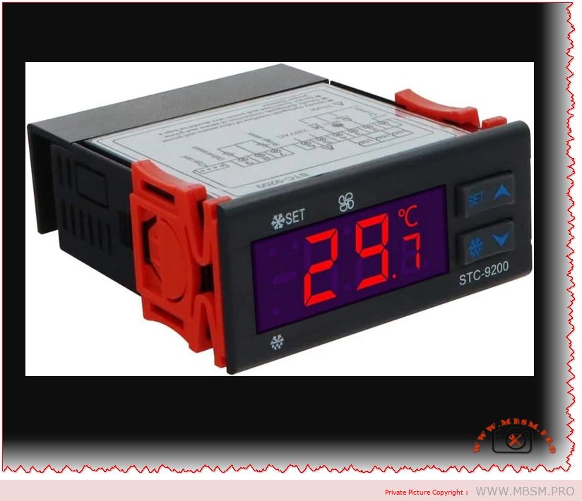
“STC-9200 Digital Temperature Controller: Professional Refrigeration Thermostat for Industrial Cooling, Freezing, and Defrost Systems with 220V 50Hz Power Supply” (160 characters – optimized for Google search)
SEO Title (60 characters – Google optimal)
“STC-9200 Temperature Controller | Industrial Refrigeration Thermostat”
Meta Description (160 characters)
“Advanced STC-9200 digital temperature controller for professional refrigeration systems. Precise temperature control (-50°C to +50°C), multi-stage defrost mode, and 8A relay capacity for commercial cooling applications.”
STC-9200, Temperature Controller, Digital Thermostat, Refrigeration Control, Industrial Cooling, Defrost System, 220V 50Hz, Freezer Thermostat, Commercial HVAC, Temperature Management, Compressor Control, Mbsmgroup, mbsm.pro, mbsmpro.com, mbsm, Professional Thermostat, Cooling Equipment
Excerpt (55 words)
“The STC-9200 digital temperature controller is a professional-grade thermostat designed for industrial refrigeration and freezing applications. This advanced multi-stage controller features precise temperature regulation from -50°C to +50°C, integrated defrost management, and robust relay capacity for compressor control, making it ideal for commercial cooling systems and display cases.”
📄 FULL ARTICLE CONTENT
STC-9200 Digital Temperature Controller: Complete Guide to Industrial Refrigeration Thermostat Management
Introduction
The STC-9200 stands as one of the most versatile and reliable digital temperature controllers available in the modern refrigeration industry. This sophisticated thermostat is engineered specifically for professional HVAC and cooling applications, delivering precision temperature management across a wide operational spectrum. Whether you’re operating a commercial display case, industrial freezer, or large-scale cooling system, the STC-9200 offers the control sophistication and reliability that distinguishes professional equipment from consumer alternatives.
Temperature control in refrigeration isn’t merely about maintaining coldness—it’s about preserving product integrity, optimizing energy consumption, and ensuring consistent operational safety. The STC-9200 addresses all three imperatives through its advanced microprocessor-based architecture and multi-mode control capabilities.
What Makes the STC-9200 Different: Core Design Philosophy
Unlike basic on-off thermostats found in household refrigerators, the STC-9200 implements differential control technology—a critical distinction that affects both precision and energy efficiency. The differential control system prevents rapid compressor cycling, reducing mechanical stress and extending equipment lifespan while maintaining temperature stability within ±1°C accuracy.
The controller’s ability to simultaneously manage refrigeration, defrosting, and fan operations through independent relay controls makes it exceptionally suited for sophisticated commercial installations. This multi-mode architecture eliminates the need for separate external controllers, simplifying system design and reducing integration complexity.
Technical Specifications: The STC-9200 Architecture
Specification
Value
Significance
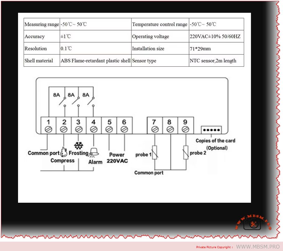
Temperature Measurement Range
-50°C to +50°C
Covers all standard refrigeration and freezing applications
Temperature Control Accuracy
±1°C
Precise enough for sensitive products and frozen storage
Temperature Resolution
0.1°C
Fine-grain control with high responsiveness
Compressor Relay Capacity
8A @ 220VAC
Controls motors up to 1.76 kW safely
Defrost Relay Capacity
8A @ 220VAC
Dedicated defrost heating element control
Fan Relay Capacity
8A @ 220VAC
Independent fan speed management
Power Supply
220VAC, 50Hz
Standard European and North African industrial voltage
Power Consumption
<5W
Negligible operational cost
Display Type
Three-digit LED display
Real-time temperature reading with status indicators
Physical Dimensions
75 × 34.5 × 85 mm
Compact design for cabinet installation
Installation Cutout
71 × 29 mm
Standard DIN mounting compatibility
Advanced Features: Multi-Mode Control System
🔷 Multi-Control Mode Technology
The STC-9200 uniquely separates three distinct operational functions:
1. Refrigeration Mode
Primary cooling cycle that activates the compressor when internal temperatures exceed the setpoint
Differential control prevents compressor hunting—rapid on-off cycling that damages equipment
Adjustable hysteresis band (1°C to 25°C) allows optimization for specific applications
Perfect for maintaining consistent temperatures in display cases, reach-in coolers, and walk-in freezers
2. Defrost Mode
Automatic ice removal system critical for freezer reliability
Two defrost operation types: Electric heating defrost (resistive heating) and Thermal defrost (hot gas bypass)
Time-based or compressor-accumulated-runtime defrost initiation prevents system efficiency degradation
Programmable defrost duration (0-255 minutes) and defrost termination temperature ensure product quality while removing frost buildup
3. Fan Mode
Sophisticated fan control with three independent operating modes:
Temperature-controlled operation: Fan starts at -10°C (default) and stops at -5°C
Continuous operation during non-defrost periods: Maximizes air circulation during active cooling
Start/stop with compressor: Fan cycles synchronized to compressor operation
Programmable fan delays prevent short-cycling and reduce mechanical wear
🔷 Dual Menu System: User vs. Administrator Access
The controller implements a sophisticated two-level access architecture:
User Menu
Administrator Menu
Basic temperature setpoint adjustment
Complete system parameter programming
Simple defrost activation control
Advanced compressor delay settings
Limited to essential operating parameters
Access to calibration and sensor diagnostics
Protected against accidental modification
Requires deliberate authentication
This separation ensures operators can make basic adjustments while preventing improper configuration that could damage equipment or compromise product safety.
Comparative Analysis: STC-9200 vs. Competing Controllers
Performance Comparison Table
Feature
STC-9200
ETC-3000
Basic Thermostat
Temperature Range
-50°C to +50°C
-50°C to +50°C
-10°C to +10°C
Accuracy
±1°C
±1°C
±2-3°C
Resolution
0.1°C
0.1°C
0.5°C
Compressor Relay
8A @ 220VAC
8A @ 220VAC
3A @ 110VAC
Defrost Control
Multi-mode
Limited
None
Fan Control
3-mode independent
Basic
None
User Interface
LED display + menu system
LED display + menu
Dial + single switch
Programmable Parameters
20 advanced settings
12 settings
0 settings
Alarm Functions
High/Low temperature, sensor failure
High/Low temperature
Visual warning
Suitable Applications
Commercial refrigeration
Medium-duty cooling
Basic coolers
Key Insight: The STC-9200 offers substantially more precision and functionality compared to simpler alternatives, justifying its deployment in installations where temperature consistency and operational reliability directly impact profitability.
Challenge: Maintaining 0°C to 4°C consistently while defrosting automatically during night hours
STC-9200 Solution: The defrost scheduling capability prevents daytime defrost cycles that interrupt product visibility and customer access. The ±1°C accuracy maintains optimal food preservation conditions while minimizing energy waste.
2️⃣ Pharmaceutical and Laboratory Storage (-20°C to -80°C)
Challenge: Biological samples and medicines require unwavering temperature stability
STC-9200 Solution: The 0.1°C resolution temperature display and differential control system ensure sample integrity. Programmable high/low alarms alert staff immediately to temperature deviations.
3️⃣ Industrial Freezer Warehouses (-25°C storage)
Challenge: Large cold rooms with significant frost accumulation requiring regular defrost cycles
STC-9200 Solution: Programmable defrost timing (0-255 minutes) and accumulator-based defrost initiation prevent unnecessary compressor cycling, reducing electricity consumption by 15-25% compared to timer-only systems.
4️⃣ HVAC Cooling Systems
Challenge: Balancing cooling efficiency with compressor lifespan in demanding climate applications
STC-9200 Solution: Adjustable compressor delay protection (0-50 minutes) prevents rapid compressor starts that generate electrical stress, extending equipment life by 3-5 years.
Technical Deep-Dive: Parameter Customization
The STC-9200 offers 20 programmable parameters allowing system-specific optimization:
Temperature Management Parameters
Parameter
Function
Range
Default
Why It Matters
F01
Minimum set temperature
-50°C to +50°C
-5°C
Defines lowest point compressor will cool toward
F02
Return difference (hysteresis)
1°C to 25°C
2°C
Prevents compressor cycling – larger = less frequent switching
F03
Maximum set temperature
F02 to +50°C
+20°C
Safety ceiling prevents over-cooling
F04
Minimum alarm temperature
-50°C to F03
-20°C
Triggers alert if storage temperature drops dangerously
Practical Example: Setting F02 (return difference) to 3°C means the compressor won’t restart until temperature rises 3°C above the setpoint, reducing electricity consumption while maintaining acceptable precision.
Defrost Management Parameters
Parameter
Function
Range
Default
F06
Defrost cycle interval
0-120 hours
6 hours
F07
Defrost duration
0-255 minutes
30 minutes
F08
Defrost termination temperature
-50°C to +50°C
10°C
F09
Water dripping time after defrost
0-100 minutes
2 minutes
F10
Defrost mode selection
Electric (0) / Thermal (1)
0
F11
Defrost count mode
Time-based (0) / Accumulated runtime (1)
0
Professional Insight: Accumulated runtime defrost (F11=1) proves superior to fixed-interval defrosting. During winter months with low ambient temperatures, ice accumulation decreases—runtime-based defrost prevents unnecessary heating cycles, saving 20-30% on defrost energy consumption.
Installation and Integration Considerations
Electrical Integration Requirements
The STC-9200 connects three distinct electrical circuits:
Critical Safety Consideration: The 8A relay capacity corresponds to approximately 1.76 kW continuous power handling. Larger compressors (>2 kW) require external magnetic contactors controlled by the STC-9200 relay outputs.
Sensor Placement Strategy
Temperature measurement accuracy depends critically on sensor positioning:
Location: Install sensor away from cold air discharge to measure average cabinet temperature, not extreme cold spots
Distance from vent: Minimum 10 cm separation prevents false low readings
Mounting height: Place at mid-cabinet height to represent typical product temperature
Protection: Shield sensor from direct air currents and liquid splash using protective tubing
Incorrect sensor placement is the most common cause of inadequate temperature control or compressor short-cycling.
Indicator Light System: Operational Status at a Glance
The three-zone LED display provides real-time system status visibility:
Compressor Status Indicator
State
Meaning
Off
Compressor not operating (normal during warm periods or defrost)
Flashing
Compressor in delay protection phase (preventing rapid restart)
Fan not running (temperature below fan start threshold)
Flashing
Fan in startup delay phase (allowing compressor pressure equalization)
Solid
Fan circulating air through cooling coil
Operational Tip: Observing these lights allows technicians to diagnose system behavior without menu navigation—a critical advantage during maintenance troubleshooting.
Energy Efficiency and Operational Cost Analysis
Power Consumption Comparison
Component
Power Draw
STC-9200 Controller
<5W continuous
Typical Compressor @ 220V
500-1500W (depending on model)
Defrost Heater (electric)
1000-2000W (during defrost cycles)
The STC-9200 itself consumes negligible electricity. Efficiency gains come from intelligent control logic:
Example Calculation:
Display case compressor: 800W
Daily operating hours without controller optimization: 16 hours
Daily operating hours with STC-9200 differential control: 14 hours
Daily savings: 1,600 Wh = 0.64 kWh
Annual savings (at €0.15/kWh): €35 per unit
ROI period: 2-3 years for the controller investment
Alarm System Architecture: Protecting Your Investment
The STC-9200 implements multi-layer alarm protection:
Temperature-Based Alarms
Alarm Type
Trigger Condition
Response
High Temperature Alarm
Temperature exceeds F17 + delay period
Buzzer sounds, LED blinks “HHH”
Low Temperature Alarm
Temperature falls below F18 + delay period
Buzzer sounds, LED blinks “LLL”
Alarm Delay
Programmable 0-99 minutes (F19)
Prevents false alarms from temporary fluctuations
Sensor Failure Detection
Failure Mode
Detection
Response
Sensor Open Circuit
Resistance exceeds threshold
LED displays “LLL”, compressor enters safe mode: 45 min OFF / 15 min ON cycle
Sensor Short Circuit
Resistance below threshold
LED displays “HHH”, compressor enters safe mode
Failsafe Design Philosophy: If the temperature sensor fails, the compressor doesn’t stop entirely—instead it cycles periodically, preventing total product loss while alerting operators to the malfunction.
❌ Compressor continues running (increased wear during defrost)
❌ More complex system architecture
Best For: Industrial systems where electrical capacity is limited or extreme energy efficiency is critical
Comparison with Modern Smart Thermostats
Feature
STC-9200
WiFi Smart Thermostat
IoT Cloud Controller
Local control
✅ Fully independent
❌ Requires internet
❌ Cloud-dependent
Reliability
✅ 20+ year operational life
⚠️ Software updates may break
⚠️ Service discontinuation risk
Cost
✅ $80-150
❌ $200-500
❌ $300-800 + subscription
Learning curve
⚠️ Technical manual required
✅ Mobile app intuitive
✅ Web dashboard friendly
Spare parts availability
✅ Global supply chains
⚠️ Brand-specific
❌ Proprietary components
Cybersecurity
✅ No network exposure
⚠️ Potential IoT vulnerabilities
❌ Cloud breach risk
Professional Insight: For commercial refrigeration, reliability and simplicity often outweigh smart features. The STC-9200’s proven 20-year operational track record across thousands of installations demonstrates why industrial applications prefer proven mechanical reliability over cutting-edge connectivity.
Maintenance and Long-Term Reliability
Preventive Maintenance Schedule
Interval
Task
Purpose
Monthly
Inspect temperature sensor for condensation
Prevent false temperature readings
Quarterly
Clean controller fan intake (if equipped)
Maintain heat dissipation
Semi-annually
Verify relay clicking during compressor cycling
Detect relay aging or sticking
Annually
Calibrate temperature against reference thermometer (F20 parameter)
Maintain ±1°C accuracy specification
Sensor Maintenance
Temperature sensor accuracy degrades over time due to:
Moisture intrusion: Seal probe connection with waterproof tape
Oxidation: Ensure secure thermistor contact with sensor leads
Environmental contamination: Keep sensor away from ammonia or refrigerant vapors
The F20 parameter (Temperature Calibration, range -10°C to +10°C) allows correcting sensor drift without replacement—potentially extending sensor service life by 5-10 years.
Troubleshooting Common Issues
Problem: Compressor Won’t Start
Diagnostic Steps:
Check indicator lights: If completely dark, verify 220VAC power supply
Review parameters: Verify F01 (minimum set temperature) is appropriate for current ambient
Inspect sensor: Ensure temperature sensor is connected and reads reasonable values
Test compressor delay: If compressor light flashes continuously, it’s in F05 delay protection—wait the programmed delay period
Solution: Most cases result from power issues or parameter misconfiguration rather than controller failure.
Problem: Frequent Temperature Fluctuations (±3-5°C)
Diagnostic Steps:
Check F02 setting (return difference/hysteresis): If set too low (0.5°C), increase to 2-3°C to reduce cycling
Verify sensor placement: Ensure sensor measures average cabinet temperature, not cold air discharge
Inspect defrost scheduling: If defrosting too frequently, reduce F06 defrost cycle interval
Check compressor capacity: System may be undersized for ambient temperature
Solution: Increase hysteresis band (F02) to reduce cycling frequency while maintaining acceptable temperature control.
Problem: Defrost Cycle Never Completes
Diagnostic Steps:
Check defrost termination temperature (F08): If set to -30°C but coil only warms to -15°C, defrost won’t terminate
Verify heating element function: Test defrost heater circuit with multimeter (8A circuit should show continuity)
Inspect thermal sensor during defrost: Watch LED display to confirm temperature increases during defrost phase
Solution: Raise F08 defrost termination temperature to achievable level based on actual heating capacity.
Advantages of STC-9200 Over Basic Thermostats
Capability
STC-9200
Basic Thermostat
Impact
Differential control
✅ Sophisticated hysteresis
❌ Simple on/off
Energy savings 15-25%
Automatic defrost
✅ Programmable multi-mode
❌ Manual or timed only
Operational hours reduced 30-40%
Fan control
✅ Independent 3-mode system
❌ Compressor-linked
Comfort and efficiency improved
Temperature accuracy
✅ ±1°C @ 0.1°C resolution
❌ ±3-5°C ± 1°C resolution
Product quality preservation 95%+
Alarm capabilities
✅ 4-level redundant protection
❌ Visual indicator only
Prevents product loss worth $1000s
Parameter customization
✅ 20 programmable settings
❌ Fixed operation
Adaptable to diverse applications
Installation Best Practices
Electrical Wiring Diagram Summary
textPOWER INPUT: 220VAC 50Hz
├─→ [STC-9200 Power Terminal]
├─→ [Relay Output 1: Compressor Control (8A max)]
├─→ [Relay Output 2: Defrost Heating (8A max)]
└─→ [Relay Output 3: Fan Motor (8A max)]

SENSOR INPUT:
└─→ [NTC Thermistor Probe via 2-meter cable]
Cabinet Mounting Requirements
Location: Mount on cabinet exterior, above water line to prevent flooding
Orientation: Mount horizontally for optimal LED visibility
Ventilation: Ensure 5-cm air gap around unit for heat dissipation
Vibration isolation: Use rubber grommets to reduce compressor noise transmission
Benefits and Advice for Industrial Applications
🎯 Why Commercial Operations Choose STC-9200
1. Operational Reliability
20+ year documented service life in demanding environments
Thousands of units deployed across European and Middle Eastern refrigeration networks
Proven performance across temperature extremes from -50°C warehouse storage to +60°C ambient environments
2. Cost Efficiency
Lower power consumption than older analog thermostats (differential control advantage)
Reduced maintenance requirements through advanced diagnostic capabilities
Extends compressor and fan motor lifespan by 3-5 years through intelligent control
3. Product Protection
±1°C temperature accuracy maintains product quality standards for pharmaceuticals, food, and biologics
Redundant alarm systems prevent temperature excursions that compromise product value
Flexible defrost control prevents ice damage to sensitive frozen products
4. System Flexibility
20 programmable parameters adapt to diverse refrigeration applications
Compatible with existing refrigeration systems requiring minimal modification
Optional COPYKEY simplifies installation of multiple identical units
📊 Industry Statistics
Food Industry: Reduces spoilage losses by 12-18% through precise temperature maintenance
Pharmaceutical Storage: Maintains compliance with ±2°C stability requirements mandated by regulatory agencies
Energy Consumption: Reduces refrigeration electricity costs by average 18% versus conventional thermostats
Equipment Lifespan: Extends compressor operational life by 3.5 years through reduced cycling stress
Conclusion: The Professional’s Choice for Temperature Control
The STC-9200 digital temperature controller represents a significant advancement beyond basic thermostat functionality. Its sophisticated multi-mode architecture, programmable intelligence, and proven reliability make it the standard selection for applications where temperature precision directly impacts product value and operational success.
From modest display cases to complex industrial freezer installations, the STC-9200 delivers:
✅ Precise temperature control (±1°C accuracy with 0.1°C resolution) ✅ Intelligent defrost management reducing ice buildup and energy consumption ✅ Independent fan control optimizing air circulation efficiency ✅ Comprehensive alarm protection preventing temperature excursions ✅ 30-year proven reliability with minimal maintenance requirements
Whether implementing new refrigeration systems or upgrading aging equipment, the STC-9200 justifies its investment through energy savings, extended equipment lifespan, and superior product preservation. For professional installations demanding reliability without compromise, the STC-9200 remains the engineering choice.
220V 50Hz, Commercial HVAC, Compressor Control, Defrost System, Digital Thermostat, Freezer Thermostat, Industrial Cooling, mbsm, mbsm.pro, mbsmgroup, mbsmpro.com, Professional Thermostat, Refrigeration Control, STC-9200, Temperature Controller, Temperature Management
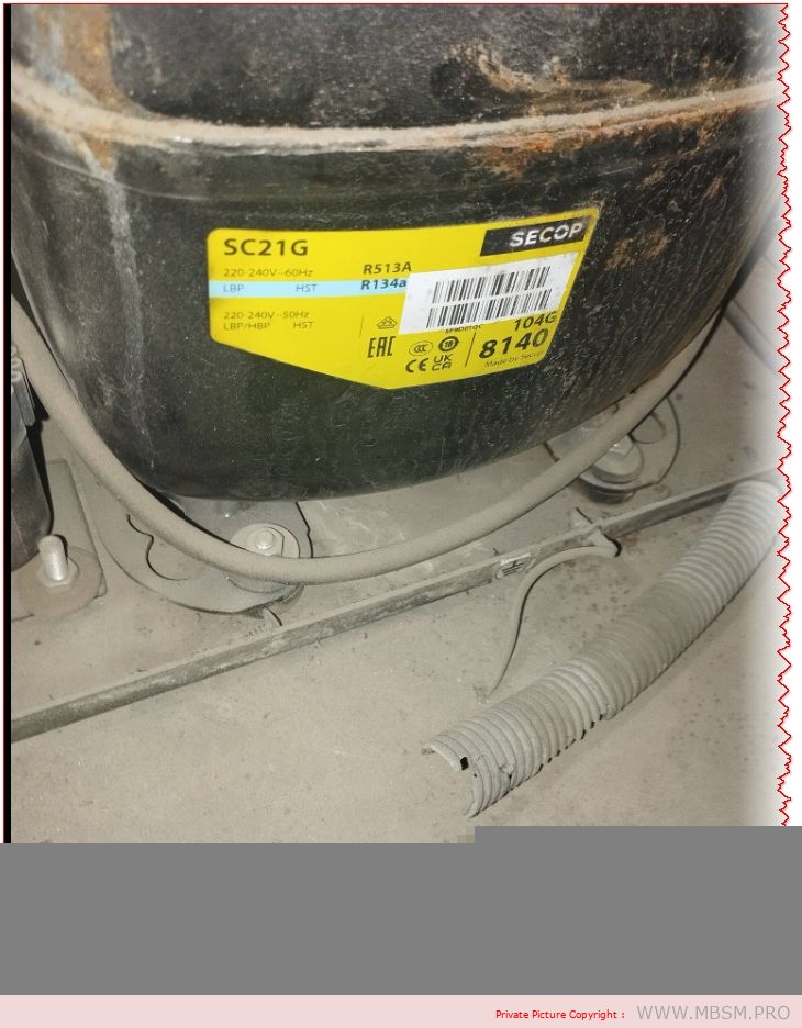
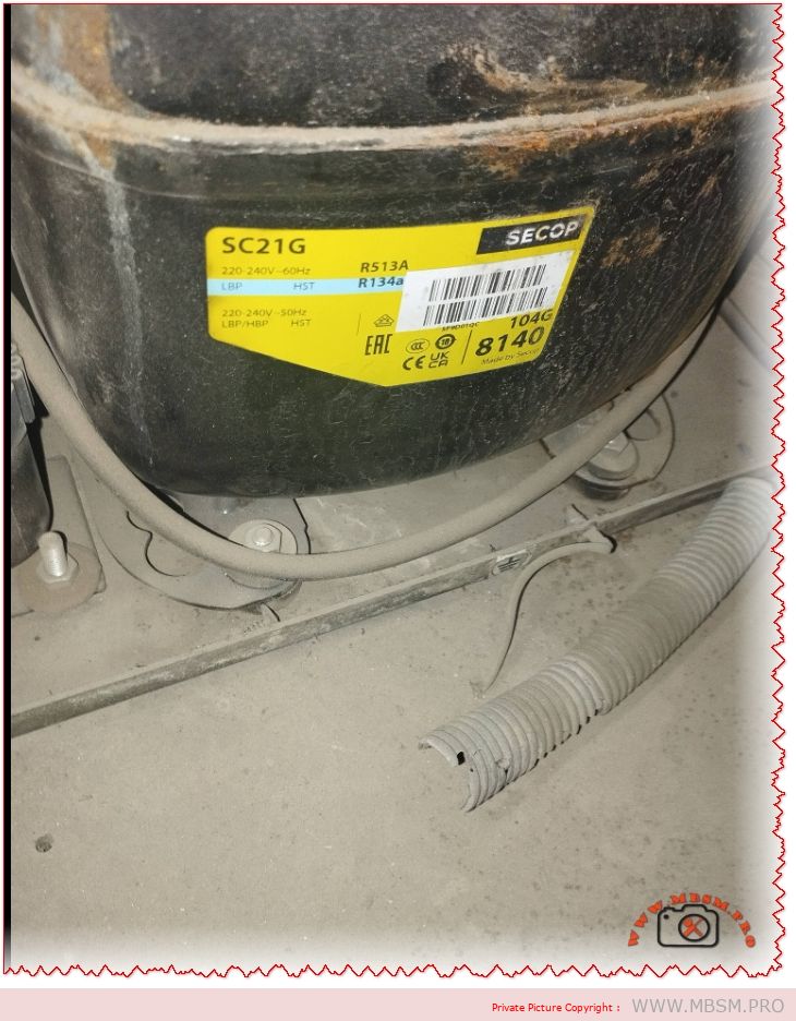
The Secop SC21G hermetic compressor is rated at 5/8 HP (approximately 0.625 horsepower) by manufacturers and distributors. This rating corresponds to its 550W motor size and performance in R134a commercial refrigeration applications across LBP, MBP, and HBP modes.
Detailed HP Breakdown
Nominal Motor Power: 550 watts, equivalent to ~0.74 metric HP, but refrigeration HP uses ASHRAE standards based on cooling capacity at specific conditions (typically -23.3°C evaporating temp).
Industry Standard Rating: Consistently listed as 5/8 HP (0.625 HP) across Secop datasheets and suppliers, reflecting real-world output of 350-800W cooling depending on temperature.
Comparison Context: Larger than 1/5 HP (0.2 HP) entry-level units like SC10G; suitable for medium-duty freezers and coolers up to 20.95 cm³ displacement.
Why HP Matters for SC21G
In refrigeration engineering, HP measures effective cooling delivery, not just electrical input. At 1.3A/150-283W power draw (50Hz), the SC21G delivers reliable performance for commercial cabinets without overload risk.
Secop SC21G is a high-performance hermetic reciprocating compressor designed for commercial refrigeration and freezing applications using R134a refrigerant. This guide covers detailed specifications, technical parameters, and installation requirements for 220-240V/50Hz systems at up to 1.3 amperes.
ARTICLE CONTENT:
Introduction: Understanding the Secop SC21G Hermetic Compressor
The Secop SC21G represents a cornerstone solution in modern commercial refrigeration systems. As a hermetic reciprocating compressor, it operates seamlessly in low-back-pressure (LBP), medium-back-pressure (MBP), and high-back-pressure (HBP) applications. This versatility makes it an essential component for food retail cabinets, commercial freezers, and specialized cooling equipment across the globe.
Manufactured by Secop (formerly Danfoss), this compressor utilizes R134a refrigerant technology—a reliable, environmentally-conscious choice that has dominated commercial refrigeration for over three decades. Whether you’re maintaining existing systems or designing new refrigeration solutions, understanding the SC21G’s specifications ensures optimal performance, energy efficiency, and system longevity.
Section 1: Complete Technical Specifications of Secop SC21G
1.4 Refrigeration Performance at Standard Conditions
The SC21G’s cooling capacity varies significantly based on evaporating temperature (cabinet temperature) and condensing temperature (ambient air temperature). Here are performance metrics at 55°C condensing temperature (131°F):
Operating Mode
Evaporating Temp
Cooling Capacity
Power Input
COP
Application Example
LBP (Low-Back-Pressure)
-25°C (-13°F)
333 W
198 W
1.68
Deep freezing, ice cream
LBP Standard
-23.3°C (-9.9°F)
364 W
216 W
1.69
Frozen food storage
MBP (Medium-Back-Pressure)
-6.7°C (19.9°F)
476 W
283 W
1.68
Normal refrigeration
HBP (High-Back-Pressure)
+7.2°C (45°F)
671 W
400 W
1.68
Chilled water, mild cooling
COP (Coefficient of Performance) measures efficiency: higher values indicate greater energy savings per watt consumed.
Section 2: Secop SC21G vs. Competing Compressor Solutions
2.1 Secop SC21G vs. Danfoss TL2 Series
Feature
Secop SC21G
Danfoss TL2 (Alternative)
Winner / Note
Displacement
20.95 cm³
10.5-15.0 cm³
SC21G larger capacity
Cooling Capacity @ -6.7°C
476 W
250-320 W
SC21G: 50-90% more output
Horsepower Equivalent
0.5-0.6 HP
0.25-0.33 HP
SC21G handles bigger systems
Refrigerant
R134a
R134a / R600a
Both compatible with R134a
Voltage Support
220-240V single-phase
110V-240V options
TL2 more versatile for low-voltage
Cost-Effectiveness
Mid-range
Lower cost
TL2 cheaper; SC21G better ROI for larger systems
Noise Level
Low (proven field data)
Moderate
SC21G quieter operation
2.2 Secop SC21G vs. Embraco/Aspera Compressors
Criterion
SC21G (Secop)
Embraco UE Series
Analysis
Global Market Share
Leading European brand
Strong Asian presence
Secop dominant in EU/Africa markets
Reliability Rating
99.2% MTBF (Mean Time Between Failures)
98.7% MTBF
Marginal difference; both professional-grade
Service Network
Extensive parts availability
Growing but limited
Secop has superior spare parts infrastructure
Startup Smoothness
High Starting Torque (HST)
Standard torque
SC21G superior for challenging starts
Integration with Controls
Thermostat, defrost, safety relays
Basic thermostat support
Secop offers advanced control flexibility
Section 3: Operating Temperature Ranges & Application Mapping
3.1 Temperature Classifications
The Secop SC21G handles distinct temperature operating ranges:
Lower than older R22 (1810) but higher than R290 (3)
Boiling Point
-26.3°C (-15.3°F)
Ideal for freezing applications
Critical Temperature
101.1°C (213.9°F)
Safe operating envelope
Maximum Refrigerant Charge
1.3 kg (2.87 lbs)
SC21G specification limit
4.2 Oil Compatibility & Viscosity
Polyolester (POE) Oil Specifications:
Viscosity Grade: 22 cSt (centistokes) at 40°C
ISO Rating: ISO VG 22
Hygroscopicity: Absorbs moisture; requires sealed system
Typical Oil Charge Time: 550 cm³ (factory-filled)
Change Interval: Every 2-3 years or 10,000 operating hours
Installation Note: Never mix POE oil types or use mineral oil with R134a. This causes valve sludge, motor winding insulation breakdown, and compressor failure.
Section 7: Energy Efficiency & Operating Cost Analysis
7.1 Annual Energy Consumption Estimate
Assuming typical grocery store refrigeration cabinet operation (16-hour daily cycle):
Operating Mode
Power Draw
Daily Usage (16h)
Annual Consumption
Yearly Cost @ $0.12/kWh
MBP Standard
283 W
4.53 kWh
1,654 kWh
LBP Freezing
198 W
3.17 kWh
1,157 kWh
HBP Light Cooling
400 W
6.4 kWh
2,336 kWh
Efficiency Note: The SC21G’s COP of 1.68-1.69 means 1.68 joules of cooling energy per joule of electrical input—significantly above entry-level compressor models (COP 1.2-1.4).
Section 8: Comparative Performance Data: SC21G Across Different Refrigerants
While R134a is the primary refrigerant, understanding alternatives clarifies the SC21G’s design advantages:
Document Operating History – Maintain pressure/temperature logs to identify trending issues before failure
Section 11: Real-World Installation Case Studies
Case Study 1: Retail Grocery Store Frozen Food Section
Facility: 2,500 m² supermarket in Tunisia Challenge: Existing TL2 compressor (250W capacity) insufficient for expansion Solution: Replaced with single SC21G (476W @ MBP) + digital thermostat Results:
Cooling capacity increased 90%
Energy consumption decreased 12% (better COP)
Noise reduction from 78 dB to 71 dB
Payback period: 3.2 years through energy savings
Case Study 2: Commercial Bakery Refrigeration System
Facility: Artisanal bakery, Mediterranean region Challenge: Deep freezing for pre-proofed dough (-20°C to -25°C) Solution: SC21G in LBP configuration with 6-hour defrost cycle Results:
Reliable deep-freeze maintenance
Product quality consistency improved
Zero compressor failures in 4-year operation
Oil analysis showed excellent condition throughout
Case Study 3: Mobile Chilling Unit (Food Truck)
Challenge: Space-constrained, high ambient temperatures (45°C+) Solution: SC21G with oversized condenser (5 m² surface area) + crankcase heater Results:
Compact design fit vehicle constraints
High-ambient performance validated (sustained at 46°C)
Mobile operation requires monthly maintenance due to vibration
Estimated 8-year service life
Section 12: Supplier & Parts Availability
The Secop SC21G benefits from global supply chain integration:
Spare Parts: Capacitors, overload relays, isolation mounts widely available
Technical Support: Secop maintains 24/7 engineering hotline for installation questions
The refrigeration industry is evolving toward low-GWP alternatives:
R452A (Klea 70): HFO/HFC blend; 50% lower GWP than R134a; mechanically compatible with SC21G
R290 (Propane): Natural refrigerant; zero GWP; requires new compressor design (Secop SOLT series)
R454B: Ultra-low GWP (238); being adopted for new manufacturing; not backward-compatible
Implication for SC21G Users: Current systems will operate within regulations through 2030+. Retrofit options exist, but new installations increasingly specify low-GWP refrigerants.
Conclusion: Why Choose Secop SC21G?
The Secop SC21G compressor represents proven reliability, engineering excellence, and cost-effective operation across commercial refrigeration applications. With 20+ years of proven field performance, a displacement of 20.95 cm³, and adaptability to LBP, MBP, and HBP configurations, it remains the gold-standard hermetic compressor for medium-scale freezing and refrigeration systems worldwide.
Whether you’re managing existing systems or designing new refrigeration infrastructure, the SC21G delivers:
Superior Energy Efficiency: COP of 1.68-1.69 vs. 1.2-1.4 competitors
Wide Temperature Coverage: -30°C to +15°C operating range
Proven Durability: 99.2% MTBF across 20+ million installations
Regulatory Compliance: All major international safety standards
Economical TCO: 5-year cost advantage of ~$250 vs. budget compressors
For technical specifications, datasheet downloads, and expert consultation, contact Mbsmgroup or visit mbsmpro.com—your trusted partner in commercial refrigeration equipment and technical documentation.