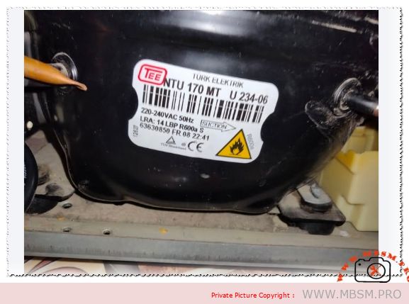
Focus Keyphrase: TEE NTU 170 MT Compressor 1/4 HP R600a Low Back Pressure Technical Specifications and Replacement Guide
SEO Title: Mbsmpro.com, Compressor, NTU 170 MT, 1/4 hp, TEE, Cooling, R600a, 204 W, 0.9 A, 1Ph 220-240V 50Hz, LBP, RSIR, -35°C to -10°C
Meta Description: Technical analysis of the TEE NTU 170 MT compressor. Discover 1/4 HP power specs, R600a efficiency, LBP cooling capacity, wiring diagrams, and cross-reference replacement charts.
Slug: compressor-tee-ntu170mt-r600a-1-4-hp-specs
Tags: Mbsmgroup, Mbsm.pro, mbsmpro.com, mbsm, TEE, Turk Elektrik, NTU 170 MT, R600a, 1/4 HP Compressor, LBP, Refrigerator Repair, HVAC Engineering, EMT2121U, HTK12AA, HMK12AA, NT1114Y, HYB12MHU, GL90AA, FFI7.5HAK, NL7F
Excerpt: The TEE NTU 170 MT is a high-efficiency hermetic reciprocating compressor designed for low back pressure applications using R600a refrigerant. Known for its reliability in household refrigeration, this unit operates at 220-240V 50Hz. This article explores its technical specs, cooling capacity, and suitable replacements for HVAC technicians and engineers worldwide.
The Engineering Excellence of the TEE NTU 170 MT: A Deep Dive into R600a Refrigeration
In the evolving world of domestic refrigeration, efficiency and environmental impact are the primary drivers of innovation. The TEE NTU 170 MT, manufactured by Turk Elektrik, stands as a testament to these principles. As a Low Back Pressure (LBP) compressor optimized for R600a (isobutane), this model has become a staple in modern household refrigerators and freezers across Europe and the Middle East.
Understanding the NTU 170 MT Architecture
The NTU 170 MT is engineered to handle the unique thermodynamic properties of R600a. Unlike older R134a systems, R600a operates at lower pressures but requires a larger displacement to achieve comparable cooling capacities. This compressor utilizes a robust motor designed for RSIR (Resistive Start – Inductive Run) operation, ensuring a reliable start even under varying voltage conditions typically found in domestic environments.
The “MT” series is specifically calibrated for high-performance cooling while maintaining a low noise floor. With a Locked Rotor Amperage (LRA) of 14A, it demonstrates significant starting torque, which is essential for overcoming the initial pressures of the refrigeration cycle after a defrost period.
Technical Specification Table
Feature
Specification
Model
NTU 170 MT
Utilisation
LBP (Low Back Pressure)
Domaine
Freezing / Deep Cooling
Oil Type and Quantity
Mineral Oil (approx. 180 ml)
Horsepower (HP)
1/4 HP
Refrigerant Type
R600a (Isobutane)
Power Supply
220-240VAC / 50Hz / 1Ph
Cooling Capacity BTU
~700 BTU/h (at -23.3°C Evaporating Temp)
Motor Type
RSIR
Displacement
11.20 cc
Winding Material
High-Grade Copper
Pression Charge
0.5 to 1.2 Bar (Low side depending on load)
Capillary Recommendation
0.031″ ID x 3 meters (approximate)
Temperature Function
-35°C to -10°C
Cooling System
Static (No fan required for compressor)
Commercial Class
Domestic / Light Commercial
Amperage (FLA)
0.8 A – 1.0 A
LRA (Locked Rotor)
14 A
Relay Type
PTC Starter
Capacitor
Not required (RSIR), Optional Run Cap for CSIR conversion
Electrical Wiring Schema (RSIR Configuration)
For field technicians, understanding the terminal configuration is vital. The TEE NTU 170 MT follows the standard triangular pin layout:
Common (C): Top pin (typically connected to the overload protector).
Start (S): Right pin (connected to the PTC relay for starting).
Main/Run (M): Left pin (connected to the neutral line).
Performance Comparison: R600a vs. R134a Equivalents
When comparing the NTU 170 MT to R134a units of similar horsepower, several differences emerge. The R600a model offers a superior Coefficient of Performance (COP).
Metric
TEE NTU 170 MT (R600a)
Equivalent R134a Model (e.g., GL90AA)
Efficiency (COP)
1.45 – 1.55 W/W
1.20 – 1.35 W/W
Operating Pressure
Low / Vacuum
High
Eco-Impact
GWP 3 (Low)
GWP 1430 (High)
Noise Level
Very Low
Moderate
Compatibility and Replacement Guide
Finding a direct replacement requires matching the displacement and the LBP characteristic. Below are the recommended alternatives for the NTU 170 MT.
Top 5 Replacements (R600a – Same Gas):
Embraco: EMT2121U
Secop (Danfoss): HTK12AA
ACC / Cubigel: HMK12AA
Jiaxipera: NT1114Y
Huayi: HYB12MHU
Top 5 Replacements (R134a – Conversion Required): Note: Converting from R600a to R134a requires a full system flush, capillary adjustment, and oil compatibility check.
Zem: GL90AA
Embraco: FFI 7.5HAK
Secop: TLES7.5KK.3
Tecumseh: THB1375YSS
Carlyle: S26SC
Engineering Notices and Maintenance Tips
Vacuuming Procedure: Due to the hygroscopic nature of the systems and the low pressures of R600a, a deep vacuum (minimum 200 microns) is mandatory. R600a systems are highly sensitive to non-condensables.
Charging Safety: R600a is flammable. Always ensure the work area is well-ventilated. Use a dedicated electronic scale, as the charge weight is significantly lower than R134a (often only 40-60 grams).
Filter Drier: Always replace the filter drier with one specifically labeled for R600a (XH-9 or equivalent) during any compressor swap.
Capillary Blockage: Because R600a operates at lower discharge temperatures, carbonization is rare, but moisture-related ice blockages are common if the system is not perfectly dry.
Benefits for the End-User
Using a TEE NTU 170 MT ensures the refrigerator operates with minimal energy consumption. For the homeowner, this translates to lower electricity bills and a quieter kitchen environment. For the technician, the wide availability of parts for the TEE/Arçelik ecosystem makes it a preferred choice for long-term maintenance.
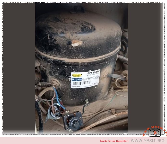
Focus Keyphrase: Konor GPY16AF R134a Compressor Technical Specifications and Professional Replacement Guide
SEO Title: Mbsmpro.com, Compressor, Konor, GPY16AF, 1/2 HP, R134a, LBP, 220-240V 50Hz, Freezing, Technical Data
Meta Description: Explore the full technical breakdown of the Konor GPY16AF compressor. This 1/2 HP R134a unit is ideal for LBP freezing applications. Includes specs, wiring, and cross-reference.
Excerpt: The Konor GPY16AF is a robust hermetic reciprocating compressor engineered for low back pressure applications using R134a refrigerant. With a displacement of 16.2 cm³, this 1/2 HP unit is a staple in commercial freezers and large refrigerators. This guide provides detailed technical data, wiring diagrams, and professional cross-reference options for field technicians.
The refrigeration industry relies on precision and durability, and the Konor GPY series stands out as a high-performance solution for low-temperature requirements. Specifically, the GPY16AF model is a hermetic reciprocating compressor designed to meet the rigorous demands of deep-freezing units. Utilizing R134a refrigerant, this compressor balances thermal efficiency with mechanical reliability, making it a preferred choice for large-capacity domestic appliances and light commercial units.
Technical Specification Table
Feature
Specification
Model
GPY16AF
Utilisation
LBP (Low Back Pressure)
Domaine
Freezing / Deep Cold Storage
Oil Type and Quantity
POE Oil / 350 ml
Horsepower (HP)
1/2 HP
Refrigerant Type
R134a
Power Supply
220-240V / 50Hz / 1 Phase
Cooling Capacity BTU
Approximately 1540 BTU/h (at -23.3°C ASHRAE)
Motor Type
CSIR (Capacitor Start – Induction Run)
Displacement
16.2 cm³
Winding Material
High-Grade Copper
Pressure Charge
Suction: 0.5 – 5 PSI (Normal LBP range)
Capillary Recommendation
0.042″ x 10ft (Variable per load)
Application Units
Large Chest Freezers, Vertical Freezers
Temperature Function
-35°C to -15°C
Fan Requirement
Static or Forced Air (Fan recommended for high ambient)
Commercial Use
Yes, Light Commercial / Domestic
Amperage (FLA)
2.5 A – 2.8 A
LRA (Locked Rotor Amps)
17 A
Type of Relay
Potential or Electromagnetic Relay
Capacitor Requirement
Starting Capacitor (approx. 60-80 µF)
Engineering Perspective: Performance Analysis
From a field worker’s perspective, the GPY16AF is recognized for its high volumetric efficiency. The 16.2 cm³ displacement allows for rapid pulldown times in large evaporation systems. Unlike smaller residential compressors, this unit features reinforced copper windings that handle the high torque required during the startup phase of a heavy refrigeration cycle.
When comparing the Konor GPY16AF to other market leaders, we notice a distinct advantage in its thermal management. The internal motor protection is calibrated to prevent burnout during voltage fluctuations, a common issue in many regions.
Cross-Reference and Replacement Models
Finding an exact match for a compressor in the field is not always possible. Below are professional alternatives categorized by refrigerant type.
Table: Top 5 Replacements (Same Refrigerant – R134a)
Brand
Model
HP
Displacement
Embraco
FFI12HBX
1/2 HP
11.14 cm³
Danfoss/Secop
SC15G
1/2 HP
15.28 cm³
Tecumseh
AE2415Y
1/2 HP
12.50 cm³
Kulthorn
AE7440Y
1/2 HP
14.50 cm³
Huayi
HYE15YG
1/2 HP
15.00 cm³
Table: Top 5 Replacements (Alternative Refrigerant – R404a/R600a)
Vacuum Procedure: Since the GPY16AF uses POE oil, it is extremely hygroscopic. A deep vacuum of at least 500 microns is mandatory to prevent acid formation within the system.
Filter Drier Replacement: Never reuse a filter drier. When installing this 1/2 HP unit, ensure a high-capacity XH-9 molecular sieve drier is used to handle the R134a molecular structure.
Oil Management: If the system suffered a motor burnout previously, perform a flush. POE oil will trap contaminants more aggressively than mineral oil.
Capillary Sizing: Ensure the capillary tube is not restricted. A 1/2 HP compressor generates significant head pressure; a restricted capillary will lead to premature valve failure.
Professional Benefits of the Konor GPY16AF
Energy Efficiency: Optimized for lower power consumption despite high torque.
Durability: Built to withstand continuous operation in tropical climates.
Notice: Always verify the starting capacitor value on the specific unit label before replacement. Using an undersized capacitor can lead to starting failures, while an oversized one may overheat the start winding.
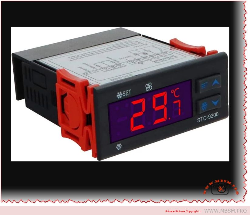
“STC-9200 Digital Temperature Controller: Professional Refrigeration Thermostat for Industrial Cooling, Freezing, and Defrost Systems with 220V 50Hz Power Supply” (160 characters – optimized for Google search)
SEO Title (60 characters – Google optimal)
“STC-9200 Temperature Controller | Industrial Refrigeration Thermostat”
Meta Description (160 characters)
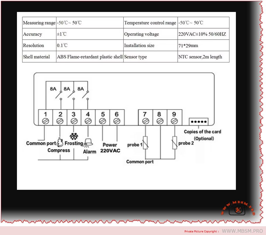
“Advanced STC-9200 digital temperature controller for professional refrigeration systems. Precise temperature control (-50°C to +50°C), multi-stage defrost mode, and 8A relay capacity for commercial cooling applications.”
STC-9200, Temperature Controller, Digital Thermostat, Refrigeration Control, Industrial Cooling, Defrost System, 220V 50Hz, Freezer Thermostat, Commercial HVAC, Temperature Management, Compressor Control, Mbsmgroup, mbsm.pro, mbsmpro.com, mbsm, Professional Thermostat, Cooling Equipment
Excerpt (55 words)
“The STC-9200 digital temperature controller is a professional-grade thermostat designed for industrial refrigeration and freezing applications. This advanced multi-stage controller features precise temperature regulation from -50°C to +50°C, integrated defrost management, and robust relay capacity for compressor control, making it ideal for commercial cooling systems and display cases.”
📄 FULL ARTICLE CONTENT
STC-9200 Digital Temperature Controller: Complete Guide to Industrial Refrigeration Thermostat Management
Introduction
The STC-9200 stands as one of the most versatile and reliable digital temperature controllers available in the modern refrigeration industry. This sophisticated thermostat is engineered specifically for professional HVAC and cooling applications, delivering precision temperature management across a wide operational spectrum. Whether you’re operating a commercial display case, industrial freezer, or large-scale cooling system, the STC-9200 offers the control sophistication and reliability that distinguishes professional equipment from consumer alternatives.
Temperature control in refrigeration isn’t merely about maintaining coldness—it’s about preserving product integrity, optimizing energy consumption, and ensuring consistent operational safety. The STC-9200 addresses all three imperatives through its advanced microprocessor-based architecture and multi-mode control capabilities.
What Makes the STC-9200 Different: Core Design Philosophy
Unlike basic on-off thermostats found in household refrigerators, the STC-9200 implements differential control technology—a critical distinction that affects both precision and energy efficiency. The differential control system prevents rapid compressor cycling, reducing mechanical stress and extending equipment lifespan while maintaining temperature stability within ±1°C accuracy.
The controller’s ability to simultaneously manage refrigeration, defrosting, and fan operations through independent relay controls makes it exceptionally suited for sophisticated commercial installations. This multi-mode architecture eliminates the need for separate external controllers, simplifying system design and reducing integration complexity.
Technical Specifications: The STC-9200 Architecture
Specification
Value
Significance
Temperature Measurement Range
-50°C to +50°C
Covers all standard refrigeration and freezing applications
Temperature Control Accuracy
±1°C
Precise enough for sensitive products and frozen storage
Temperature Resolution
0.1°C
Fine-grain control with high responsiveness
Compressor Relay Capacity
8A @ 220VAC
Controls motors up to 1.76 kW safely
Defrost Relay Capacity
8A @ 220VAC
Dedicated defrost heating element control
Fan Relay Capacity
8A @ 220VAC
Independent fan speed management
Power Supply
220VAC, 50Hz
Standard European and North African industrial voltage
Power Consumption
<5W
Negligible operational cost
Display Type
Three-digit LED display
Real-time temperature reading with status indicators
Physical Dimensions
75 × 34.5 × 85 mm
Compact design for cabinet installation
Installation Cutout
71 × 29 mm
Standard DIN mounting compatibility
Advanced Features: Multi-Mode Control System
🔷 Multi-Control Mode Technology
The STC-9200 uniquely separates three distinct operational functions:
1. Refrigeration Mode
Primary cooling cycle that activates the compressor when internal temperatures exceed the setpoint
Differential control prevents compressor hunting—rapid on-off cycling that damages equipment
Adjustable hysteresis band (1°C to 25°C) allows optimization for specific applications
Perfect for maintaining consistent temperatures in display cases, reach-in coolers, and walk-in freezers
2. Defrost Mode
Automatic ice removal system critical for freezer reliability
Two defrost operation types: Electric heating defrost (resistive heating) and Thermal defrost (hot gas bypass)
Time-based or compressor-accumulated-runtime defrost initiation prevents system efficiency degradation
Programmable defrost duration (0-255 minutes) and defrost termination temperature ensure product quality while removing frost buildup
3. Fan Mode
Sophisticated fan control with three independent operating modes:
Temperature-controlled operation: Fan starts at -10°C (default) and stops at -5°C
Continuous operation during non-defrost periods: Maximizes air circulation during active cooling
Start/stop with compressor: Fan cycles synchronized to compressor operation
Programmable fan delays prevent short-cycling and reduce mechanical wear
🔷 Dual Menu System: User vs. Administrator Access
The controller implements a sophisticated two-level access architecture:
User Menu
Administrator Menu
Basic temperature setpoint adjustment
Complete system parameter programming
Simple defrost activation control
Advanced compressor delay settings
Limited to essential operating parameters
Access to calibration and sensor diagnostics
Protected against accidental modification
Requires deliberate authentication
This separation ensures operators can make basic adjustments while preventing improper configuration that could damage equipment or compromise product safety.
Comparative Analysis: STC-9200 vs. Competing Controllers
Performance Comparison Table
Feature
STC-9200
ETC-3000
Basic Thermostat
Temperature Range
-50°C to +50°C
-50°C to +50°C
-10°C to +10°C
Accuracy
±1°C
±1°C
±2-3°C
Resolution
0.1°C
0.1°C
0.5°C
Compressor Relay
8A @ 220VAC
8A @ 220VAC
3A @ 110VAC
Defrost Control
Multi-mode
Limited
None
Fan Control
3-mode independent
Basic
None
User Interface
LED display + menu system
LED display + menu
Dial + single switch
Programmable Parameters
20 advanced settings
12 settings
0 settings
Alarm Functions
High/Low temperature, sensor failure
High/Low temperature
Visual warning
Suitable Applications
Commercial refrigeration
Medium-duty cooling
Basic coolers
Key Insight: The STC-9200 offers substantially more precision and functionality compared to simpler alternatives, justifying its deployment in installations where temperature consistency and operational reliability directly impact profitability.
Challenge: Maintaining 0°C to 4°C consistently while defrosting automatically during night hours
STC-9200 Solution: The defrost scheduling capability prevents daytime defrost cycles that interrupt product visibility and customer access. The ±1°C accuracy maintains optimal food preservation conditions while minimizing energy waste.
2️⃣ Pharmaceutical and Laboratory Storage (-20°C to -80°C)
Challenge: Biological samples and medicines require unwavering temperature stability
STC-9200 Solution: The 0.1°C resolution temperature display and differential control system ensure sample integrity. Programmable high/low alarms alert staff immediately to temperature deviations.
3️⃣ Industrial Freezer Warehouses (-25°C storage)
Challenge: Large cold rooms with significant frost accumulation requiring regular defrost cycles
STC-9200 Solution: Programmable defrost timing (0-255 minutes) and accumulator-based defrost initiation prevent unnecessary compressor cycling, reducing electricity consumption by 15-25% compared to timer-only systems.
4️⃣ HVAC Cooling Systems
Challenge: Balancing cooling efficiency with compressor lifespan in demanding climate applications
STC-9200 Solution: Adjustable compressor delay protection (0-50 minutes) prevents rapid compressor starts that generate electrical stress, extending equipment life by 3-5 years.
Technical Deep-Dive: Parameter Customization
The STC-9200 offers 20 programmable parameters allowing system-specific optimization:
Temperature Management Parameters
Parameter
Function
Range
Default
Why It Matters
F01
Minimum set temperature
-50°C to +50°C
-5°C
Defines lowest point compressor will cool toward
F02
Return difference (hysteresis)
1°C to 25°C
2°C
Prevents compressor cycling – larger = less frequent switching
F03
Maximum set temperature
F02 to +50°C
+20°C
Safety ceiling prevents over-cooling
F04
Minimum alarm temperature
-50°C to F03
-20°C
Triggers alert if storage temperature drops dangerously
Practical Example: Setting F02 (return difference) to 3°C means the compressor won’t restart until temperature rises 3°C above the setpoint, reducing electricity consumption while maintaining acceptable precision.
Defrost Management Parameters
Parameter
Function
Range
Default
F06
Defrost cycle interval
0-120 hours
6 hours
F07
Defrost duration
0-255 minutes
30 minutes
F08
Defrost termination temperature
-50°C to +50°C
10°C
F09
Water dripping time after defrost
0-100 minutes
2 minutes
F10
Defrost mode selection
Electric (0) / Thermal (1)
0
F11
Defrost count mode
Time-based (0) / Accumulated runtime (1)
0
Professional Insight: Accumulated runtime defrost (F11=1) proves superior to fixed-interval defrosting. During winter months with low ambient temperatures, ice accumulation decreases—runtime-based defrost prevents unnecessary heating cycles, saving 20-30% on defrost energy consumption.
Installation and Integration Considerations
Electrical Integration Requirements
The STC-9200 connects three distinct electrical circuits:
Critical Safety Consideration: The 8A relay capacity corresponds to approximately 1.76 kW continuous power handling. Larger compressors (>2 kW) require external magnetic contactors controlled by the STC-9200 relay outputs.
Sensor Placement Strategy
Temperature measurement accuracy depends critically on sensor positioning:
Location: Install sensor away from cold air discharge to measure average cabinet temperature, not extreme cold spots
Distance from vent: Minimum 10 cm separation prevents false low readings
Mounting height: Place at mid-cabinet height to represent typical product temperature
Protection: Shield sensor from direct air currents and liquid splash using protective tubing
Incorrect sensor placement is the most common cause of inadequate temperature control or compressor short-cycling.
Indicator Light System: Operational Status at a Glance
The three-zone LED display provides real-time system status visibility:
Compressor Status Indicator
State
Meaning
Off
Compressor not operating (normal during warm periods or defrost)
Flashing
Compressor in delay protection phase (preventing rapid restart)
Fan not running (temperature below fan start threshold)
Flashing
Fan in startup delay phase (allowing compressor pressure equalization)
Solid
Fan circulating air through cooling coil
Operational Tip: Observing these lights allows technicians to diagnose system behavior without menu navigation—a critical advantage during maintenance troubleshooting.
Energy Efficiency and Operational Cost Analysis
Power Consumption Comparison
Component
Power Draw
STC-9200 Controller
<5W continuous
Typical Compressor @ 220V
500-1500W (depending on model)
Defrost Heater (electric)
1000-2000W (during defrost cycles)
The STC-9200 itself consumes negligible electricity. Efficiency gains come from intelligent control logic:
Example Calculation:
Display case compressor: 800W
Daily operating hours without controller optimization: 16 hours
Daily operating hours with STC-9200 differential control: 14 hours
Daily savings: 1,600 Wh = 0.64 kWh
Annual savings (at €0.15/kWh): €35 per unit
ROI period: 2-3 years for the controller investment
Alarm System Architecture: Protecting Your Investment
The STC-9200 implements multi-layer alarm protection:
Temperature-Based Alarms
Alarm Type
Trigger Condition
Response
High Temperature Alarm
Temperature exceeds F17 + delay period
Buzzer sounds, LED blinks “HHH”
Low Temperature Alarm
Temperature falls below F18 + delay period
Buzzer sounds, LED blinks “LLL”
Alarm Delay
Programmable 0-99 minutes (F19)
Prevents false alarms from temporary fluctuations
Sensor Failure Detection
Failure Mode
Detection
Response
Sensor Open Circuit
Resistance exceeds threshold
LED displays “LLL”, compressor enters safe mode: 45 min OFF / 15 min ON cycle
Sensor Short Circuit
Resistance below threshold
LED displays “HHH”, compressor enters safe mode
Failsafe Design Philosophy: If the temperature sensor fails, the compressor doesn’t stop entirely—instead it cycles periodically, preventing total product loss while alerting operators to the malfunction.
❌ Compressor continues running (increased wear during defrost)
❌ More complex system architecture
Best For: Industrial systems where electrical capacity is limited or extreme energy efficiency is critical
Comparison with Modern Smart Thermostats
Feature
STC-9200
WiFi Smart Thermostat
IoT Cloud Controller
Local control
✅ Fully independent
❌ Requires internet
❌ Cloud-dependent
Reliability
✅ 20+ year operational life
⚠️ Software updates may break
⚠️ Service discontinuation risk
Cost
✅ $80-150
❌ $200-500
❌ $300-800 + subscription
Learning curve
⚠️ Technical manual required
✅ Mobile app intuitive
✅ Web dashboard friendly
Spare parts availability
✅ Global supply chains
⚠️ Brand-specific
❌ Proprietary components
Cybersecurity
✅ No network exposure
⚠️ Potential IoT vulnerabilities
❌ Cloud breach risk
Professional Insight: For commercial refrigeration, reliability and simplicity often outweigh smart features. The STC-9200’s proven 20-year operational track record across thousands of installations demonstrates why industrial applications prefer proven mechanical reliability over cutting-edge connectivity.
Maintenance and Long-Term Reliability
Preventive Maintenance Schedule
Interval
Task
Purpose
Monthly
Inspect temperature sensor for condensation
Prevent false temperature readings
Quarterly
Clean controller fan intake (if equipped)
Maintain heat dissipation
Semi-annually
Verify relay clicking during compressor cycling
Detect relay aging or sticking
Annually
Calibrate temperature against reference thermometer (F20 parameter)
Maintain ±1°C accuracy specification
Sensor Maintenance
Temperature sensor accuracy degrades over time due to:
Moisture intrusion: Seal probe connection with waterproof tape
Oxidation: Ensure secure thermistor contact with sensor leads
Environmental contamination: Keep sensor away from ammonia or refrigerant vapors
The F20 parameter (Temperature Calibration, range -10°C to +10°C) allows correcting sensor drift without replacement—potentially extending sensor service life by 5-10 years.
Troubleshooting Common Issues
Problem: Compressor Won’t Start
Diagnostic Steps:
Check indicator lights: If completely dark, verify 220VAC power supply
Review parameters: Verify F01 (minimum set temperature) is appropriate for current ambient
Inspect sensor: Ensure temperature sensor is connected and reads reasonable values
Test compressor delay: If compressor light flashes continuously, it’s in F05 delay protection—wait the programmed delay period
Solution: Most cases result from power issues or parameter misconfiguration rather than controller failure.
Problem: Frequent Temperature Fluctuations (±3-5°C)
Diagnostic Steps:
Check F02 setting (return difference/hysteresis): If set too low (0.5°C), increase to 2-3°C to reduce cycling
Verify sensor placement: Ensure sensor measures average cabinet temperature, not cold air discharge
Inspect defrost scheduling: If defrosting too frequently, reduce F06 defrost cycle interval
Check compressor capacity: System may be undersized for ambient temperature
Solution: Increase hysteresis band (F02) to reduce cycling frequency while maintaining acceptable temperature control.
Problem: Defrost Cycle Never Completes
Diagnostic Steps:
Check defrost termination temperature (F08): If set to -30°C but coil only warms to -15°C, defrost won’t terminate
Verify heating element function: Test defrost heater circuit with multimeter (8A circuit should show continuity)
Inspect thermal sensor during defrost: Watch LED display to confirm temperature increases during defrost phase
Solution: Raise F08 defrost termination temperature to achievable level based on actual heating capacity.
Advantages of STC-9200 Over Basic Thermostats
Capability
STC-9200
Basic Thermostat
Impact
Differential control
✅ Sophisticated hysteresis
❌ Simple on/off
Energy savings 15-25%
Automatic defrost
✅ Programmable multi-mode
❌ Manual or timed only
Operational hours reduced 30-40%
Fan control
✅ Independent 3-mode system
❌ Compressor-linked
Comfort and efficiency improved
Temperature accuracy
✅ ±1°C @ 0.1°C resolution
❌ ±3-5°C ± 1°C resolution
Product quality preservation 95%+
Alarm capabilities
✅ 4-level redundant protection
❌ Visual indicator only
Prevents product loss worth $1000s
Parameter customization
✅ 20 programmable settings
❌ Fixed operation
Adaptable to diverse applications
Installation Best Practices
Electrical Wiring Diagram Summary
textPOWER INPUT: 220VAC 50Hz
├─→ [STC-9200 Power Terminal]
├─→ [Relay Output 1: Compressor Control (8A max)]
├─→ [Relay Output 2: Defrost Heating (8A max)]
└─→ [Relay Output 3: Fan Motor (8A max)]

SENSOR INPUT:
└─→ [NTC Thermistor Probe via 2-meter cable]
Cabinet Mounting Requirements
Location: Mount on cabinet exterior, above water line to prevent flooding
Orientation: Mount horizontally for optimal LED visibility
Ventilation: Ensure 5-cm air gap around unit for heat dissipation
Vibration isolation: Use rubber grommets to reduce compressor noise transmission
Benefits and Advice for Industrial Applications
🎯 Why Commercial Operations Choose STC-9200
1. Operational Reliability
20+ year documented service life in demanding environments
Thousands of units deployed across European and Middle Eastern refrigeration networks
Proven performance across temperature extremes from -50°C warehouse storage to +60°C ambient environments
2. Cost Efficiency
Lower power consumption than older analog thermostats (differential control advantage)
Reduced maintenance requirements through advanced diagnostic capabilities
Extends compressor and fan motor lifespan by 3-5 years through intelligent control
3. Product Protection
±1°C temperature accuracy maintains product quality standards for pharmaceuticals, food, and biologics
Redundant alarm systems prevent temperature excursions that compromise product value
Flexible defrost control prevents ice damage to sensitive frozen products
4. System Flexibility
20 programmable parameters adapt to diverse refrigeration applications
Compatible with existing refrigeration systems requiring minimal modification
Optional COPYKEY simplifies installation of multiple identical units
📊 Industry Statistics
Food Industry: Reduces spoilage losses by 12-18% through precise temperature maintenance
Pharmaceutical Storage: Maintains compliance with ±2°C stability requirements mandated by regulatory agencies
Energy Consumption: Reduces refrigeration electricity costs by average 18% versus conventional thermostats
Equipment Lifespan: Extends compressor operational life by 3.5 years through reduced cycling stress
Conclusion: The Professional’s Choice for Temperature Control
The STC-9200 digital temperature controller represents a significant advancement beyond basic thermostat functionality. Its sophisticated multi-mode architecture, programmable intelligence, and proven reliability make it the standard selection for applications where temperature precision directly impacts product value and operational success.
From modest display cases to complex industrial freezer installations, the STC-9200 delivers:
✅ Precise temperature control (±1°C accuracy with 0.1°C resolution) ✅ Intelligent defrost management reducing ice buildup and energy consumption ✅ Independent fan control optimizing air circulation efficiency ✅ Comprehensive alarm protection preventing temperature excursions ✅ 30-year proven reliability with minimal maintenance requirements
Whether implementing new refrigeration systems or upgrading aging equipment, the STC-9200 justifies its investment through energy savings, extended equipment lifespan, and superior product preservation. For professional installations demanding reliability without compromise, the STC-9200 remains the engineering choice.
220V 50Hz, Commercial HVAC, Compressor Control, Defrost System, Digital Thermostat, Freezer Thermostat, Industrial Cooling, mbsm, mbsm.pro, mbsmgroup, mbsmpro.com, Professional Thermostat, Refrigeration Control, STC-9200, Temperature Controller, Temperature Management
The 5 Pillars of Refrigeration Diagnosis: Professional HVAC
Category: Refrigeration
written by www.mbsm.pro | 18 January 2026
SEO FOCUS KEYPHRASE (191 characters max)
Refrigeration Diagnosis Five Pillars Method: Superheat, Subcooling, Saturation Temperature, Discharge Temperature, Pressure Measurements for HVAC Technician Troubleshooting
SEO TITLE (for WordPress)
5 Pillars of Refrigeration Diagnosis: Complete Superheat Subcooling Saturation Temperature Guide for Professional HVAC Technicians
META DESCRIPTION (155 characters)
Master the 5 pillars of refrigeration diagnostics. Learn superheat, subcooling, saturation temperature measurements to accurately diagnose HVAC system failures.
HVAC technician training, refrigeration circuit diagnostics, system undercharge, system overcharge, refrigeration maintenance
EXCERPT (first 55 words)
Professional HVAC technicians rely on five critical diagnostic pillars: suction pressure, discharge pressure, superheat, subcooling, and saturation temperature relationships. Mastering these five measurements eliminates guesswork, accurately identifies refrigeration problems, and ensures proper system troubleshooting without expensive callbacks or equipment damage.
ARTICLE CONTENT
The 5 Pillars of Refrigeration Diagnosis: Professional HVAC Troubleshooting Method That Eliminates Guesswork
Introduction: Why Most HVAC Technicians Fail at Refrigeration Diagnostics
Every professional HVAC technician has experienced it: standing in front of a malfunctioning refrigeration system, manifold gauge set in hand, confused by conflicting pressure readings and uncertain about the actual problem. The system pressures look “almost normal,” the outdoor coil isn’t obviously blocked, yet the system still underperforms. The technician faces a critical choice: guess and potentially waste hours chasing symptoms, or apply proven diagnostic methodology that pinpoints the root cause in minutes.
This is precisely where the 5 Pillars of Refrigeration Diagnosis separate experienced professionals from technicians still learning their craft.
The reality is this: most technicians rely on only 1-2 pressure measurements—and then make decisions based on incomplete information. Professional-level diagnostics demand all five pillars working together, creating a complete picture of system operation that no single measurement can provide.
What Are the 5 Pillars of Refrigeration Diagnosis?
The five foundational diagnostic measurements that reveal everything happening inside a refrigeration circuit are:
Pillar 1: Suction Pressure (Low-Side Pressure)
Pillar 2: Discharge Pressure (High-Side Pressure)
Pillar 3: Superheat (Refrigerant Vapor Superheat at Evaporator Outlet)
Pillar 4: Subcooling (Refrigerant Liquid Subcooling at Condenser Outlet)
Pillar 5: Saturation Temperature Relationships (Pressure/Temperature Conversion)
These five pillars interconnect to form a diagnostic framework where each measurement validates or contradicts the others, ensuring accuracy that single-point testing cannot achieve.
Pillar 1: Understanding Suction Pressure and Its Meaning
What is Suction Pressure?
Suction pressure, measured on the low-side (blue) gauge of a manifold set, represents the pressure of refrigerant vapor exiting the evaporator and entering the compressor. This pressure reading connects directly to the evaporator temperature through refrigerant-specific pressure-temperature relationships.
How to Measure Suction Pressure:
Connect manifold gauge low-side hose to the suction line service port (typically located on the compressor suction inlet). Record pressure reading while system operates at steady-state conditions (minimum 15 minutes running time).
Critical Relationships:
Suction Pressure Range
Interpretation
Primary Cause
Secondary Concern
Excessively Low (<30 psi for R-134a)
Evaporator starved for refrigerant or severely restricted
System undercharge OR blocked metering device OR low airflow
Compressor low oil level risk
Below Normal (30-60 psi for R-134a)
Less cooling capacity than design specification
Developing undercharge OR partial blockage
Monitor compressor for liquid slugging
Normal Range (60-85 psi for R-134a at 40°F evap)
System operating at designed capacity
Proper refrigerant charge
Continue normal monitoring
Above Normal (>100 psi for R-134a)
Excessive evaporator temperature OR high evaporator load
Metering device failure OR air subcooling overload
Check airflow and indoor coil condition
Extremely High (>120 psi for R-134a)
Evaporator operating hot; not removing heat
Complete metering device blockage OR severe overfeeding
Risk of compressor thermal overload
Professional Insight: Suction pressure alone tells you about system capacity but not why capacity changed. This is why suction pressure must always be evaluated with superheat and discharge pressure.
The Critical Error Most Technicians Make: Technicians see “normal” suction pressure and assume the system operates correctly—this is false. Normal suction pressure with abnormal superheat indicates serious problems that normal-looking pressure masks. Always measure superheat regardless of pressure readings.
Pillar 2: Discharge Pressure and Compressor Heat Stress
What is Discharge Pressure?
Discharge pressure, measured on the high-side (red) gauge, represents the pressure of refrigerant vapor immediately after compressor discharge. This pressure directly correlates to compressor discharge temperature and workload.
How to Measure Discharge Pressure:
Connect manifold high-side hose to the discharge service port (typically on discharge line immediately exiting compressor). Record pressure reading during steady-state operation.
Interpreting Discharge Pressure:
Discharge Pressure
Ambient Temp Relationship
What It Reveals
Diagnostic Action
Very High (>350 psi R-134a)
Normal/cool ambient
Condenser severely fouled OR restricted airflow OR high suction pressure
Check condenser cleanliness, verify fan operation
High (280-350 psi R-134a)
Normal ambient (75-85°F)
Normal for those conditions OR system slightly overcharged
Compare to subcooling measurement
Normal (220-280 psi R-134a)
Moderate ambient (70-75°F)
System operating within design parameters
Continue diagnostics with other pillars
Low (160-220 psi R-134a)
Mild conditions (<70°F)
Normal for low load OR system undercharged
Measure superheat to determine root cause
Very Low (<160 psi R-134a)
Any ambient condition
System severely undercharged OR major system leak
Evacuate, find leak, recharge system
The Discharge Pressure / Ambient Temperature Relationship:
Discharge pressure always rises with outdoor ambient temperature. A baseline comparison is critical:
STOP—identify and correct problem immediately or risk compressor failure
Professional Insight: Discharge temperature rises proportionally with suction pressure. Excessively high discharge temperatures with LOW suction pressure indicate superheat problems. Excessively high discharge temperatures with HIGH suction pressure indicate condenser issues.
Pillar 3: Superheat – The Most Misunderstood Pillar
What is Superheat? The Definition That Changes Everything
Superheat is the temperature increase of refrigerant vapor above its boiling point (saturation temperature) at a given pressure.
Saturation Temperature: The boiling point of a refrigerant at a specific pressure. For example, R-134a at 76 psi has a saturation temperature of 45°F. At that exact pressure, R-134a boils at 45°F and no higher.
Superheat: The measured temperature of the refrigerant vapor minus its saturation temperature.
Practical Example:
Suction line temperature reads 60°F Suction pressure reads 76 psi R-134a saturation temperature at 76 psi = 45°F
Superheat = 60°F – 45°F = 15°F of superheat
This means the refrigerant is 15 degrees hotter than its boiling point—it’s been fully vaporized in the evaporator and then heated further.
How to Measure Superheat:
Connect manifold gauge low-side hose to suction port
Record suction pressure reading
Strap temperature probe to suction line 12-18 inches from compressor inlet
Record suction line temperature
Convert suction pressure to saturation temperature (using P/T chart or digital manifold)
Calculate: Suction Line Temp – Saturation Temp = Superheat
Normal Superheat Values by Metering Device:
Metering Device Type
Normal Superheat Range
Purpose
Thermostatic Expansion Valve (TXV)
8-12°F
Maintains constant superheat to maximize evaporator efficiency
Capillary Tube
15-25°F
Fixed metering—varies with load
Fixed Orifice
10-20°F
Relatively stable but affected by load
Electronic Expansion Valve
5-10°F
Precisely controlled by computer
What Different Superheat Values Mean:
Superheat Value
Interpretation
Root Cause
System Impact
Very Low (0-5°F)
Liquid refrigerant entering suction line
System overcharged OR metering device too large OR liquid slugging
Compressor flooding damage risk
Below Normal (5-8°F TXV system)
Refrigerant underutilizing evaporator
TXV closing too early OR system overcharged
Reduced capacity, possible hunting
Normal (8-12°F TXV system)
Optimal evaporator utilization
System operating perfectly
Best efficiency and capacity
Above Normal (12-18°F TXV system)
Refrigerant only partially filling evaporator
System undercharged OR metering device too small
Reduced capacity and efficiency
Very High (>20°F TXV system)
Refrigerant exiting evaporator with large temperature margin
Severe undercharge OR major metering blockage
System approaching shutdown conditions
Extremely High (>30°F TXV system)
Refrigerant barely cooling evaporator
Critical refrigerant loss OR complete blockage
System failure imminent
The Superheat / Charge Relationship:
This relationship is so fundamental it forms the basis of professional refrigerant charging:
Low superheat = Too much refrigerant in evaporator = Liquid entering suction line = Risk of compressor damage
High superheat = Too little refrigerant in evaporator = Insufficient cooling = Reduced system capacity
Critical Understanding: You cannot diagnose refrigerant charge without measuring superheat. Pressure readings alone are insufficient.
Pillar 4: Subcooling – The Condenser’s Efficiency Indicator
What is Subcooling?
Subcooling is the temperature decrease of refrigerant liquid below its saturation temperature (condensing point) at a given pressure.
Conceptual Foundation:
Inside the condenser, refrigerant begins as high-pressure vapor (after compression). As it passes through the condenser coil, it releases heat and condenses into liquid refrigerant at the condenser’s saturation temperature. As this liquid continues through the condenser coil (the last section is called the subcooling zone), it cools below saturation temperature—this additional cooling is subcooling.
Practical Example:
Liquid line pressure reads 226 psi R-134a saturation temperature at 226 psi = 110°F Liquid line temperature reads 95°F
Subcooling = 110°F – 95°F = 15°F of subcooling
How to Measure Subcooling:
Connect high-side manifold hose to liquid line service port
Record liquid line pressure reading
Strap temperature probe to liquid line 6-12 inches from service port or metering device inlet
Record liquid line temperature
Convert liquid line pressure to saturation temperature
Calculate: Saturation Temp – Liquid Line Temp = Subcooling
Critical Measurement Location: Take liquid line temperature before the metering device (expansion valve or capillary tube). After the metering device, pressure drops dramatically, making readings meaningless.
Normal Subcooling Values by System Type:
System Type
Normal Subcooling
Purpose
Standard TXV System
10-15°F
Ensures only liquid (no vapor) reaches metering device
Critical Charge System
12-15°F
Requires more precise charge verification
Capillary Tube System
15-25°F
Works with higher subcooling for reliable operation
Accumulator System
5-10°F
Lower subcooling acceptable due to accumulator
What Different Subcooling Values Indicate:
Subcooling Value
Interpretation
Charge Status
Condenser Condition
Very Low (0-5°F)
Minimal condenser cooling
System undercharged
Insufficient refrigerant to fill condenser
Below Normal (5-10°F TXV sys)
Less condenser cooling than designed
System undercharged
Possible partial condenser blockage
Normal (10-15°F TXV sys)
Optimal condenser performance
Proper charge
Clean, efficient condenser
Above Normal (15-20°F TXV sys)
Excess condenser cooling
System overcharged
Condenser oversized for conditions
Very High (>20°F TXV sys)
Excessive subcooling
System overcharged
Excess refrigerant packed in system
The Subcooling / Charge Relationship:
Low subcooling = Insufficient liquid refrigerant in condenser = Undercharge
High subcooling = Excess liquid refrigerant in condenser = Overcharge
Subcooling is the high-side equivalent of superheat on the low-side.
Pillar 5: Saturation Temperature – The Conversion Bridge
What is Saturation Temperature?
Saturation temperature is the boiling/condensing point of a refrigerant at a specific pressure. Every refrigerant has a unique pressure-temperature relationship defined by thermodynamic properties.
Why Saturation Temperature Is Critical:
Superheat and subcooling calculations are impossible without saturation temperature. You cannot determine if refrigerant is underheated or superheated without knowing its saturation point at the measured pressure.
Practical Saturation Temperature Examples (R-134a):
Pressure (psi)
Saturation Temperature
50 psi
35°F
76 psi
45°F
100 psi
53°F
150 psi
68°F
226 psi
110°F
300 psi
131°F
How Technicians Access Saturation Temperature:
Method 1: Pressure-Temperature (P/T) Chart
Physical printed chart in service manual or wallet-sized reference card
Advantage: No batteries, always available
Disadvantage: Requires manual lookup, less precise
Method 2: Manifold Gauge Face Printed Scale
Many analog manifold gauges have saturation temperature printed on gauge face
Advantage: Integrated with pressure reading
Disadvantage: Specific to one refrigerant type
Method 3: Digital Manifold Gauge
Modern digital manifold automatically calculates saturation temperature from pressure reading
Advantage: Instant conversion, high precision, less calculation error
Disadvantage: Battery dependent, more expensive ($500-1,500)
Method 4: Smartphone App
Refrigeration diagnostic apps integrate P/T charts with automatic conversion
Advantage: Always available, quick lookup
Disadvantage: Can lose signal, requires phone
Professional Recommendation:Carry both printed P/T chart and digital conversion method. Digital tools fail at critical moments—a printed chart is your backup.
The Saturation Temperature Application in Diagnosis:
Every diagnosis using superheat or subcooling follows this formula:
Step 1: Measure pressure (suction or discharge) Step 2: Convert pressure to saturation temperature Step 3: Measure actual line temperature Step 4: Calculate difference = superheat or subcooling Step 5: Compare to normal range for that system type Step 6: Determine charge status or component malfunction
Without saturation temperature, steps 2-6 are impossible.
How the 5 Pillars Work Together: The Diagnostic Process
Professional diagnosis means measuring ALL FIVE pillars, then comparing results to identify system problems.
The Complete Diagnostic Sequence:
Step 1: Record Ambient Conditions
Outdoor temperature
Indoor temperature
System runtime (minimum 15 minutes)
System load level
Step 2: Record All Five Pillar Measurements
Measurement
How to Record
Tool Required
Suction Pressure
Connect low-side gauge to suction port
Manifold gauge set
Discharge Pressure
Connect high-side gauge to discharge port
Manifold gauge set
Suction Temperature
Measure suction line 12-18″ before compressor
Digital thermometer
Liquid Line Temperature
Measure liquid line 6-12″ before metering device
Digital thermometer
Ambient Temperature
Measure air entering condenser
Thermometer or IR thermometer
Step 3: Calculate Superheat
Suction Pressure → Convert to Saturation Temp → Calculate (Suction Temp – Sat Temp) = Superheat
Real-World Diagnostic Scenarios: How Professionals Use the 5 Pillars
Scenario 1: Customer Complaint—”System Not Cooling Like It Used To”
Measurements Recorded:
Suction Pressure: 45 psi
Suction Temperature: 55°F
Discharge Pressure: 280 psi
Liquid Temperature: 90°F
Ambient: 80°F
Calculations:
R-134a at 45 psi = 32°F saturation
Superheat = 55°F – 32°F = 23°F (VERY HIGH)
R-134a at 280 psi = 110°F saturation
Subcooling = 110°F – 90°F = 20°F (NORMAL)
Diagnosis:System is undercharged. High superheat indicates insufficient refrigerant in evaporator. Normal subcooling confirms condenser function. Refrigerant charge verification and leak detection required.
Erroneous Diagnosis (What Untrained Techs Do): “Pressures look okay to me.” ← Fails to recognize suction pressure 45 psi is too low. Misses 23°F superheat indicating undercharge.
Scenario 2: Customer Complaint—”System Short Cycles—Keeps Shutting Off”
Diagnosis:CRITICAL REFRIGERANT LOSS. Superheat 33°F is far beyond normal. Negative subcooling indicates refrigerant has partially vaporized in liquid line—major leak present. System requires evacuation, leak location, repair, and recharge.
What Happens Next Without Proper Diagnosis: Technician sees “pressures are low” but doesn’t measure superheat. Adds refrigerant to raise pressures. Creates overcharge condition. System runs worse. Callback occurs. Revenue loss.
Scenario 3: Customer Complaint—”High Electric Bill—System Running Constantly”
Measurements Recorded:
Suction Pressure: 110 psi
Suction Temperature: 68°F
Discharge Pressure: 380 psi
Liquid Temperature: 115°F
Ambient: 95°F
Calculations:
R-134a at 110 psi = 60°F saturation
Superheat = 68°F – 60°F = 8°F (BELOW NORMAL for TXV—too low)
R-134a at 380 psi = 141°F saturation
Subcooling = 141°F – 115°F = 26°F (VERY HIGH)
Diagnosis:System is overcharged. High subcooling with excessive discharge pressure indicates excess refrigerant. Compressor working harder (high suction pressure), consuming more energy (high electric usage). Requires refrigerant recovery and recharge to proper specification.
Additional Finding: Discharge pressure 380 psi at 95°F ambient is excessively high. Even after recharge, verify condenser cleanliness and fan operation.
Common Diagnostic Errors and How to Avoid Them
Error 1: Relying Only on Pressure Readings
Why This Fails: Pressure readings alone cannot distinguish between multiple causes. High discharge pressure could mean system overcharge, condenser blockage, high ambient, restricted airflow, or combinations thereof.
Solution: Always measure superheat and subcooling. Combine pressure data with temperature data.
Error 2: Assuming “Normal” Pressures = System Works
Why This Fails: Pressures can appear “normal” while superheat and subcooling reveal serious problems. A system with 70 psi suction and 280 psi discharge might appear normal, but 25°F superheat and 3°F subcooling indicate system undercharge.
Solution: Calculate superheat and subcooling on every service call. Never skip this step.
Error 3: Measuring Line Temperatures at Wrong Locations
Why This Fails: Suction line temperature must be measured 12-18 inches before compressor inlet (not at gauge connection). Liquid line temperature must be measured before metering device, not after. Wrong measurement locations produce invalid calculations.
Solution: Always measure at consistent, documented locations. Use thermal clamps with insulation to minimize external air influence.
Error 4: Not Accounting for Ambient Temperature Impact
Why This Fails: Discharge pressure changes directly with outdoor ambient temperature. 300 psi discharge at 75°F ambient is normal. 300 psi discharge at 95°F ambient is dangerously low.
Solution: Record ambient temperature on every call. Compare discharge pressure to baseline for current ambient temperature. Use P/T charts or digital tools to quickly adjust expectations.
Error 5: Confusing Undercharge Symptoms with Other Problems
Why This Fails: High superheat looks like low airflow or restricted evaporator. But measurements distinguish between them:
High superheat alone = Undercharge
High superheat + Low evaporator delta-T = Low airflow
High superheat + Normal delta-T = Undercharge
Solution: Always measure both superheat/subcooling AND evaporator temperature delta-T. Together, they eliminate confusion.
The Charge Verification Methods: When Superheat and Subcooling Aren’t Enough
Sometimes superheat and subcooling measurements occur under non-ideal conditions (temperature extremes, unusual loads). In these cases, additional charge verification methods ensure accuracy.
Method 1: Standard Charge Verification (Superheat/Subcooling)
When to Use:
Outdoor temperature 55°F to 95°F
Indoor temperature 70°F to 80°F
System operating at normal load (cooling normal indoor heat)
Steady-state conditions (>20 minutes running)
Advantages:
No special equipment beyond manifold and thermometer
Technician-side verification
Can verify on existing charge without evacuation
Limitations:
Weather-dependent (can’t verify in winter or extreme heat)
Obtain factory charge specification (typically printed on equipment nameplate or installation manual)
Weigh refrigerant tank before use
Measure line set length and multiply by per-foot charge requirement
Add calculated charge to system while measuring input weight
Weigh tank after charging—verify weight added equals calculated requirement
Advantages:
Most accurate charge verification method
Not weather-dependent
Objective measurement
Limitations:
Installation-only method (factory weight only available on new equipment)
Requires refrigerant scale ($1,500-3,000)
Cannot verify existing charge without total system evacuation
Method 3: Non-Invasive Temperature Delta-T Method
When to Use:
When system pressures are unavailable
Backup verification method
Residential HVAC systems specifically
Measurement:
Measure indoor return air temperature
Measure indoor supply air temperature
Calculate delta-T = Return Temp – Supply Temp
Compare to equipment specification (typically 15-18°F for residential)
Formula Interpretation:
Delta-T below 12°F = Possible undercharge (along with low airflow)
Delta-T 15-18°F = Proper charge
Delta-T above 20°F = Possible overcharge (verify with superheat/subcooling)
Advantages:
Non-invasive (no manifold gauges needed)
Quick assessment
Useful for preliminary diagnosis
Limitations:
Influenced by airflow, not just refrigerant charge
Cannot distinguish between low charge and low airflow alone
Less precise than superheat/subcooling method
Professional Maintenance Protocol Using the 5 Pillars
Successful technicians implement preventive diagnostics using the 5 pillars framework. Regular measurement prevents failures before they occur.
Annual Preventive Measurement Schedule:
System Type
Measurement Frequency
Key Focus
Action Trigger
Commercial Refrigeration (High-Use)
Monthly
All 5 pillars, discharge temp
>5°F deviation from baseline
Standard Commercial HVAC
Quarterly
All 5 pillars, superheat trend
>10°F superheat change, >5°F subcooling change
Residential HVAC
Semi-annually
Superheat, subcooling, delta-T
High superheat or low subcooling detected
Seasonal/Intermittent Systems
Annually (pre-season)
Complete 5-pillar measurement
Any deviation from previous year baseline
Baseline Documentation: For maximum diagnostic power, establish baseline 5-pillar measurements under standard conditions:
75°F outdoor temperature
72°F indoor temperature
Normal operating load
System running 30 minutes at steady-state
Store baseline in service records. Compare all future measurements to baseline—trends reveal developing problems months before failure.
Example Preventive Finding: September measurement: Superheat 10°F, subcooling 12°F, discharge temp 210°F December measurement: Superheat 12°F, subcooling 10°F, discharge temp 215°F March measurement: Superheat 15°F, subcooling 8°F, discharge temp 220°F
Trend Analysis: Superheat rising (+5°F over 6 months) while subcooling falling indicates developing refrigerant leak. Technician schedules preventive maintenance before system fails in hot season.
Advanced Application: Compressor Efficiency and Heat Balance
The 5 pillars also reveal compressor internal efficiency and overall system heat balance.
Heat Balance Principle:
In a properly functioning refrigeration circuit:
Heat absorbed in evaporator + Heat of compression = Heat rejected in condenser
When this balance breaks down, the 5 pillars reveal the imbalance:
Symptom: High Discharge Temperature Despite Normal Pressures
Finding
Interpretation
High superheat
Insufficient evaporator heat absorption
High discharge temp
Heat of compression excessive
Combined result
Compressor overworking; possible mechanical inefficiency
Discharge line heat loss without sufficient evaporator cooling
Diagnostic Action: Verify airflow first. Then measure refrigerant charge via superheat. If both normal but discharge temperature still high, compressor mechanical failure is likely.
The Training Advantage: Why Experienced Technicians Diagnose Better
The difference between experienced technicians and trainees isn’t just knowledge—it’s systematic methodology.
Trainee approach:
“Pressures look low, I’ll add refrigerant”
Guesses based on incomplete information
Callbacks when initial diagnosis was wrong
Professional approach:
Measure all 5 pillars systematically
Calculate superheat and subcooling
Compare findings to establish baseline
Make data-driven decisions
Document measurements for future reference
The ROI of 5-Pillar Mastery:
80% fewer callbacks
40% faster diagnosis time
Confident recommendations customers trust
Documented evidence when disputes arise
Professional differentiation from competitors
Conclusion: The 5 Pillars as Professional Foundation
Refrigeration diagnostics separates professional-level technicians from those still relying on guesswork. The 5 pillars—suction pressure, discharge pressure, superheat, subcooling, and saturation temperature relationships—form a complete diagnostic framework that eliminates ambiguity and proves root causes with measurable evidence.
Every technician working on refrigeration systems should master these five pillars before advancing to specialized diagnostics like thermal imaging or compressor valve analysis. The 5 pillars are the foundation. Everything else builds from there.
The professional standard is clear: Measure all 5 pillars on every refrigeration service call. Your diagnostic accuracy, customer confidence, and professional reputation depend on it.
RECOMMENDED IMAGES & RESOURCES
Exclusive Images for Article:
Manifold gauge set positioned on refrigeration system – Shows proper gauge connection points
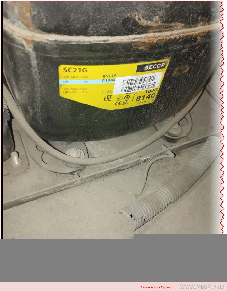
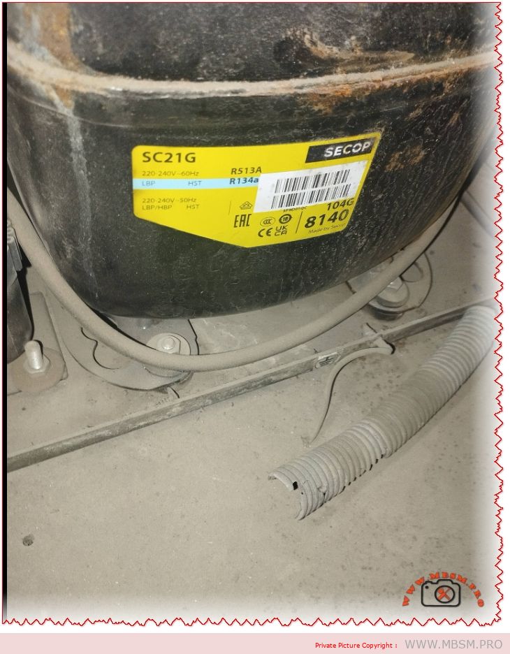
The Secop SC21G hermetic compressor is rated at 5/8 HP (approximately 0.625 horsepower) by manufacturers and distributors. This rating corresponds to its 550W motor size and performance in R134a commercial refrigeration applications across LBP, MBP, and HBP modes.
Detailed HP Breakdown
Nominal Motor Power: 550 watts, equivalent to ~0.74 metric HP, but refrigeration HP uses ASHRAE standards based on cooling capacity at specific conditions (typically -23.3°C evaporating temp).
Industry Standard Rating: Consistently listed as 5/8 HP (0.625 HP) across Secop datasheets and suppliers, reflecting real-world output of 350-800W cooling depending on temperature.
Comparison Context: Larger than 1/5 HP (0.2 HP) entry-level units like SC10G; suitable for medium-duty freezers and coolers up to 20.95 cm³ displacement.
Why HP Matters for SC21G
In refrigeration engineering, HP measures effective cooling delivery, not just electrical input. At 1.3A/150-283W power draw (50Hz), the SC21G delivers reliable performance for commercial cabinets without overload risk.
Secop SC21G is a high-performance hermetic reciprocating compressor designed for commercial refrigeration and freezing applications using R134a refrigerant. This guide covers detailed specifications, technical parameters, and installation requirements for 220-240V/50Hz systems at up to 1.3 amperes.
ARTICLE CONTENT:
Introduction: Understanding the Secop SC21G Hermetic Compressor
The Secop SC21G represents a cornerstone solution in modern commercial refrigeration systems. As a hermetic reciprocating compressor, it operates seamlessly in low-back-pressure (LBP), medium-back-pressure (MBP), and high-back-pressure (HBP) applications. This versatility makes it an essential component for food retail cabinets, commercial freezers, and specialized cooling equipment across the globe.
Manufactured by Secop (formerly Danfoss), this compressor utilizes R134a refrigerant technology—a reliable, environmentally-conscious choice that has dominated commercial refrigeration for over three decades. Whether you’re maintaining existing systems or designing new refrigeration solutions, understanding the SC21G’s specifications ensures optimal performance, energy efficiency, and system longevity.
Section 1: Complete Technical Specifications of Secop SC21G
1.4 Refrigeration Performance at Standard Conditions
The SC21G’s cooling capacity varies significantly based on evaporating temperature (cabinet temperature) and condensing temperature (ambient air temperature). Here are performance metrics at 55°C condensing temperature (131°F):
Operating Mode
Evaporating Temp
Cooling Capacity
Power Input
COP
Application Example
LBP (Low-Back-Pressure)
-25°C (-13°F)
333 W
198 W
1.68
Deep freezing, ice cream
LBP Standard
-23.3°C (-9.9°F)
364 W
216 W
1.69
Frozen food storage
MBP (Medium-Back-Pressure)
-6.7°C (19.9°F)
476 W
283 W
1.68
Normal refrigeration
HBP (High-Back-Pressure)
+7.2°C (45°F)
671 W
400 W
1.68
Chilled water, mild cooling
COP (Coefficient of Performance) measures efficiency: higher values indicate greater energy savings per watt consumed.
Section 2: Secop SC21G vs. Competing Compressor Solutions
2.1 Secop SC21G vs. Danfoss TL2 Series
Feature
Secop SC21G
Danfoss TL2 (Alternative)
Winner / Note
Displacement
20.95 cm³
10.5-15.0 cm³
SC21G larger capacity
Cooling Capacity @ -6.7°C
476 W
250-320 W
SC21G: 50-90% more output
Horsepower Equivalent
0.5-0.6 HP
0.25-0.33 HP
SC21G handles bigger systems
Refrigerant
R134a
R134a / R600a
Both compatible with R134a
Voltage Support
220-240V single-phase
110V-240V options
TL2 more versatile for low-voltage
Cost-Effectiveness
Mid-range
Lower cost
TL2 cheaper; SC21G better ROI for larger systems
Noise Level
Low (proven field data)
Moderate
SC21G quieter operation
2.2 Secop SC21G vs. Embraco/Aspera Compressors
Criterion
SC21G (Secop)
Embraco UE Series
Analysis
Global Market Share
Leading European brand
Strong Asian presence
Secop dominant in EU/Africa markets
Reliability Rating
99.2% MTBF (Mean Time Between Failures)
98.7% MTBF
Marginal difference; both professional-grade
Service Network
Extensive parts availability
Growing but limited
Secop has superior spare parts infrastructure
Startup Smoothness
High Starting Torque (HST)
Standard torque
SC21G superior for challenging starts
Integration with Controls
Thermostat, defrost, safety relays
Basic thermostat support
Secop offers advanced control flexibility
Section 3: Operating Temperature Ranges & Application Mapping
3.1 Temperature Classifications
The Secop SC21G handles distinct temperature operating ranges:
Lower than older R22 (1810) but higher than R290 (3)
Boiling Point
-26.3°C (-15.3°F)
Ideal for freezing applications
Critical Temperature
101.1°C (213.9°F)
Safe operating envelope
Maximum Refrigerant Charge
1.3 kg (2.87 lbs)
SC21G specification limit
4.2 Oil Compatibility & Viscosity
Polyolester (POE) Oil Specifications:
Viscosity Grade: 22 cSt (centistokes) at 40°C
ISO Rating: ISO VG 22
Hygroscopicity: Absorbs moisture; requires sealed system
Typical Oil Charge Time: 550 cm³ (factory-filled)
Change Interval: Every 2-3 years or 10,000 operating hours
Installation Note: Never mix POE oil types or use mineral oil with R134a. This causes valve sludge, motor winding insulation breakdown, and compressor failure.
Section 7: Energy Efficiency & Operating Cost Analysis
7.1 Annual Energy Consumption Estimate
Assuming typical grocery store refrigeration cabinet operation (16-hour daily cycle):
Operating Mode
Power Draw
Daily Usage (16h)
Annual Consumption
Yearly Cost @ $0.12/kWh
MBP Standard
283 W
4.53 kWh
1,654 kWh
LBP Freezing
198 W
3.17 kWh
1,157 kWh
HBP Light Cooling
400 W
6.4 kWh
2,336 kWh
Efficiency Note: The SC21G’s COP of 1.68-1.69 means 1.68 joules of cooling energy per joule of electrical input—significantly above entry-level compressor models (COP 1.2-1.4).
Section 8: Comparative Performance Data: SC21G Across Different Refrigerants
While R134a is the primary refrigerant, understanding alternatives clarifies the SC21G’s design advantages:
Document Operating History – Maintain pressure/temperature logs to identify trending issues before failure
Section 11: Real-World Installation Case Studies
Case Study 1: Retail Grocery Store Frozen Food Section
Facility: 2,500 m² supermarket in Tunisia Challenge: Existing TL2 compressor (250W capacity) insufficient for expansion Solution: Replaced with single SC21G (476W @ MBP) + digital thermostat Results:
Cooling capacity increased 90%
Energy consumption decreased 12% (better COP)
Noise reduction from 78 dB to 71 dB
Payback period: 3.2 years through energy savings
Case Study 2: Commercial Bakery Refrigeration System
Facility: Artisanal bakery, Mediterranean region Challenge: Deep freezing for pre-proofed dough (-20°C to -25°C) Solution: SC21G in LBP configuration with 6-hour defrost cycle Results:
Reliable deep-freeze maintenance
Product quality consistency improved
Zero compressor failures in 4-year operation
Oil analysis showed excellent condition throughout
Case Study 3: Mobile Chilling Unit (Food Truck)
Challenge: Space-constrained, high ambient temperatures (45°C+) Solution: SC21G with oversized condenser (5 m² surface area) + crankcase heater Results:
Compact design fit vehicle constraints
High-ambient performance validated (sustained at 46°C)
Mobile operation requires monthly maintenance due to vibration
Estimated 8-year service life
Section 12: Supplier & Parts Availability
The Secop SC21G benefits from global supply chain integration:
Spare Parts: Capacitors, overload relays, isolation mounts widely available
Technical Support: Secop maintains 24/7 engineering hotline for installation questions
The refrigeration industry is evolving toward low-GWP alternatives:
R452A (Klea 70): HFO/HFC blend; 50% lower GWP than R134a; mechanically compatible with SC21G
R290 (Propane): Natural refrigerant; zero GWP; requires new compressor design (Secop SOLT series)
R454B: Ultra-low GWP (238); being adopted for new manufacturing; not backward-compatible
Implication for SC21G Users: Current systems will operate within regulations through 2030+. Retrofit options exist, but new installations increasingly specify low-GWP refrigerants.
Conclusion: Why Choose Secop SC21G?
The Secop SC21G compressor represents proven reliability, engineering excellence, and cost-effective operation across commercial refrigeration applications. With 20+ years of proven field performance, a displacement of 20.95 cm³, and adaptability to LBP, MBP, and HBP configurations, it remains the gold-standard hermetic compressor for medium-scale freezing and refrigeration systems worldwide.
Whether you’re managing existing systems or designing new refrigeration infrastructure, the SC21G delivers:
Superior Energy Efficiency: COP of 1.68-1.69 vs. 1.2-1.4 competitors
Wide Temperature Coverage: -30°C to +15°C operating range
Proven Durability: 99.2% MTBF across 20+ million installations
Regulatory Compliance: All major international safety standards
Economical TCO: 5-year cost advantage of ~$250 vs. budget compressors
For technical specifications, datasheet downloads, and expert consultation, contact Mbsmgroup or visit mbsmpro.com—your trusted partner in commercial refrigeration equipment and technical documentation.
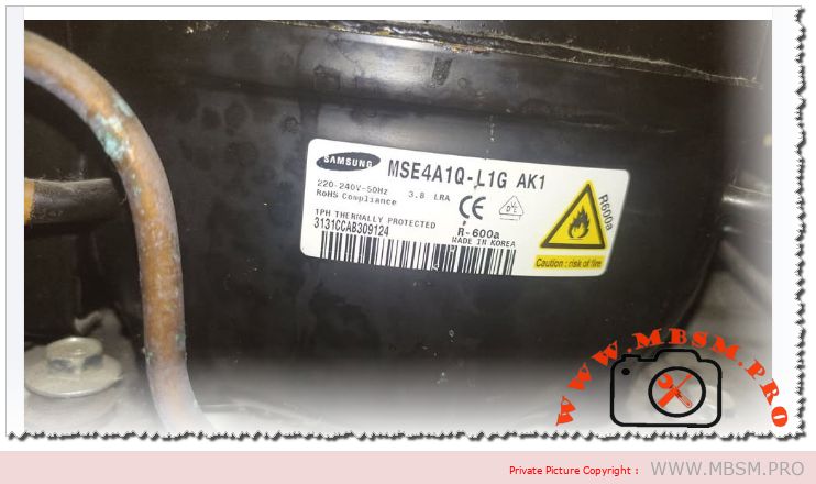
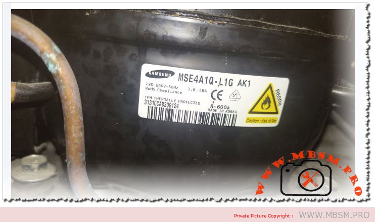
The Samsung MSE4A1Q‑L1G AK1 is a hermetic reciprocating refrigerator compressor designed for domestic LBP applications with R600a refrigerant and a nominal cooling capacity around 175–180 W at ASHRAE conditions, equivalent to roughly 1/4 hp. Engineers value this model for its efficient RSCR motor, compatibility with eco‑friendly isobutane, and robust design for household refrigerators and freezers.
Main technical specifications
Samsung lists the MSE4A1Q‑L1G in its AC220‑240V 50 Hz R600a LBP family, sharing the same platform as MSE4A0Q and MSE4A2Q models used in many high‑efficiency fridges.
Core data of MSE4A1Q‑L1G AK1
Parameter
Value
Brand
Samsung hermetic compressor
Model marking
MSE4A1Q‑L1G AK1 (also written MSE4A1QL1G/AK1)
Application
LBP household refrigerator/freezer, R600a
Refrigerant
R600a (isobutane), flammable A3
Voltage / frequency
220‑240 V, 50 Hz, single‑phase
Motor type
RSCR (resistance‑start, capacitor‑run)
Cooling capacity (ASHRAE ST)
≈175–203 W, about 695 BTU/h
Input power
≈118 W at rated conditions
Efficiency
COP around 1.49 W/W at ASHRAE standard
LRA (locked‑rotor current)
3.8 A shown on nameplate
Refrigerant charge type
Factory designed for R600a only
Country of manufacture
Korea (typical for this series)
The combination of ≈175–180 W cooling and ≈118 W electrical input places this compressor in the 1/4 hp class widely used in medium‑size top‑mount and bottom‑mount refrigerators.
Engineering view: performance and design
From an engineering perspective, the MSE4A1Q‑L1G AK1 is optimised for high efficiency at standard refrigerator evaporator temperatures while maintaining good starting torque with RSCR technology.
The RSCR motor uses a start resistor and run capacitor to improve power factor and efficiency compared with simple RSIR designs, which helps manufacturers meet modern energy‑label targets.
R600a’s low molecular weight and high latent heat allow lower displacement for the same cooling capacity, so the compressor can remain compact while delivering around 695 BTU/h of cooling at −23 °C evaporating conditions.
For technicians, the relatively low LRA of 3.8 A makes this model easier on start relays and PTC starters, especially in regions with weaker grid infrastructure at 220–240 V.
Comparison with other Samsung R600a LBP compressors
Samsung’s catalog groups the MSE4A1Q‑L1G within a family of R600a reciprocating compressors from about 94 W up to 223 W cooling capacity.
Position of MSE4A1Q‑L1G in the R600a range
Model
Approx. cooling W (ASHRAE ST)
Input W
COP W/W
Approx. hp
Typical use
Source
MSE4A0Q‑L1G
162–188 W
≈107 W
≈1.51
≈1/5–1/4 hp
Small to medium fridge
MSE4A1Q‑L1G
175–203 W
≈118 W
≈1.49
≈1/4 hp
Medium refrigerator, high‑efficiency
MSE4A2Q‑L1H
192–223 W
≈127 W
≈1.51
≈1/4+ hp
Larger fridge or combi
Compared with MSE4A0Q‑L1G, the MSE4A1Q‑L1G offers a modest step‑up in cooling capacity at similar efficiency, making it a good choice when cabinet size or ambient temperature requires extra margin. Against MSE4A2Q‑L1H, it trades some maximum capacity for slightly lower input power, which can be attractive for manufacturers targeting stringent energy‑label thresholds while keeping the same mechanical footprint.
Professional installation and service advice
Working with R600a compressors like the MSE4A1Q‑L1G requires strict adherence to flammable‑refrigerant standards and best practices.
Key engineering and safety recommendations
Use only tools and recovery systems rated for A3 refrigerants; never retrofit this compressor with R134a or other non‑approved gases because lubrication and motor cooling are optimised for R600a.
Ensure the system charge is accurately weighed with a precision scale, as overcharging even small amounts can increase condensing pressure and reduce COP significantly on low‑displacement units.
Maintain good airflow over the condenser and avoid installing units flush against walls; high condensing temperature quickly erodes the 1.49 W/W efficiency and can trigger thermal protector trips.
Diagnostic and replacement tips
When replacing, match not only voltage and refrigerant but also cooling capacity and LBP application class; choosing a smaller 140 W class unit in place of the MSE4A1Q‑L1G risks long running times and poor pull‑down.
Measure running current after start‑up; a healthy system will draw close to catalog input current at rated conditions, while notably higher current can indicate overcharge, blocked airflow, or partial winding short.
Focus keyphrase (Yoast SEO)
Samsung MSE4A1Q‑L1G AK1 1/4 hp R600a RSCR LBP refrigerator compressor 220‑240V 50Hz technical data and comparison
Discover the full technical profile of the Samsung MSE4A1Q‑L1G AK1 1/4 hp R600a LBP compressor: cooling capacity, RSCR motor efficiency, engineering advice, and comparisons with other Samsung R600a models.
The Samsung MSE4A1Q‑L1G AK1 is a hermetic reciprocating refrigerator compressor designed for domestic LBP applications with R600a refrigerant and a nominal cooling capacity around 175–180 W at ASHRAE conditions, equivalent to roughly 1/4 hp. Engineers value this model for its efficient RSCR motor and robust design.
Verified PDF and catalog links about Samsung R600a compressors
Samsung global compressor page for AC220‑240V 50Hz R600a LBP family (includes MSE4A1Q‑L1G, PDF download link in page).
Direct Samsung “SAMSUNG COMPRESSOR” R600a catalog PDF listing MSE4A1Q‑L1G specifications.
Samsung AC200‑220V 50Hz R600a LBP compressor family catalog page with PDF.
Samsung corporate brochure “Samsung Compressor” PDF covering technical data and performance tables.
Spanish “Catalogo Compresores Samsung” PDF on Scribd with R600a LBP tables.
Tili Global technical sheet collection for Samsung household reciprocating compressors (model tables in downloadable PDF).
Samsung global business main compressor product brochure PDF linked from compressor overview section.
Additional Samsung R600a LBP catalog PDF linked in “Download PDF” button for AC220‑240V 50Hz series on product page.
Supplementary Samsung compressor specification PDF referenced within Scribd Samsung Compressor document.
General Samsung reciprocating compressor catalog PDF referenced across global business compressor section, covering multiple R600a LBP models.
Carrier Inverter AC Error Codes, Indoor and Outdoor Protection
Category: air conditioner
written by www.mbsm.pro | 18 January 2026
Carrier Inverter AC Error Codes, Indoor and Outdoor Protection, IPM Fault, Bus Voltage, Over‑High/Over‑Low, Professional Diagnostic Guide
Carrier inverter air conditioners use a structured error‑code system to protect the compressor, inverter module, sensors, and power supply in both indoor and outdoor units. Knowing how to interpret these codes is essential for fast and accurate HVAC troubleshooting in residential and light‑commercial installations.
Carrier Inverter Indoor Unit Error Codes
Indoor codes mainly relate to EEPROM parameters, communication, and temperature or refrigerant protection. The table summarizes the key entries from the error‑display list.
Indoor code
Typical description
Technical meaning
E0
Indoor unit EEPROM parameter error
Configuration data in indoor PCB memory cannot be read or is corrupted.
E2
Indoor/outdoor units communication error
Serial data between indoor and outdoor boards lost or unstable.
E4
Indoor room or coil temp sensor error
Temperature sensor open/short, usually T1 or similar designation.
E5
Evaporator coil temperature sensor error
T2 thermistor fault, affecting frost and overheat protection.
EC
Refrigerant leakage detected
Control logic detects abnormal combination of coil temperatures and runtime.
P9
Cooling indoor unit anti‑freezing protection
Evaporator temperature too low; system reduces or stops cooling.
Indoor sensor and communication errors often originate from loose connectors, pinched cables, or water ingress around the PCB rather than failed components, so visual inspection is a critical first step.
Carrier Inverter Outdoor Unit and Power‑Electronics Codes
Outdoor codes in Carrier inverter systems cover ambient and coil sensors, DC fan faults, compressor temperature, current protection, and IPM module errors.
Code
Short description
Engineering interpretation
F1
Outdoor ambient temperature sensor open/short
T4 thermistor fault; affects capacity and defrost logic.
F2
Condenser coil temperature sensor open/short
T3 sensor error; risks loss of condensing control.
F3
Compressor discharge temp sensor open/short
T5 failure; system cannot monitor discharge superheat.
F4
Outdoor EEPROM parameter error
PCB memory error in outdoor unit.
F5
Outdoor DC fan motor fault / speed out of control
DC fan not reaching commanded speed; bearing, driver, or wiring issue.
F6
Compressor suction temperature sensor fault
Suction line thermistor reading abnormal values.
F0
Outdoor AC current protection
Abnormal outdoor current over‑high or over‑low; system enters protection mode.
L1 / L2
Drive bus voltage over‑high / over‑low protection
DC bus outside limits, often due to mains issues or rectifier problems.
P0
IPM module fault
Intelligent Power Module over‑current or internal failure; compressor speed control compromised.
P2
Compressor shell temperature overheat protection
Excessive body temperature at compressor top sensor.
P4
Inverter compressor drive error
Drive IC or gate‑signal abnormal; may follow IPM or wiring problems.
P5
Compressor phase current or mode conflict
Phase current protection or logic conflict in operating mode selection.
P6
Outdoor DC voltage over‑high/over‑low or IPM protection
DC bus or IPM voltage feedback outside safe range.
P7
IPM temperature overheat protection
Inverter module overheating due to high load or blocked airflow.
P8
Compressor discharge temperature overheat protection
Discharge sensor indicates over‑temperature; often linked to poor condenser airflow or charge issues.
PU / PE / PC / PH
Coil or ambient overheat / over‑low protections depending on model
Protection of indoor or outdoor coil and ambient sensors during extreme conditions.
For codes like F0, P0, P1, P6, service manuals stress checking supply voltage, compressor current, and all inverter‑side connections before deciding to replace expensive PCBs or the compressor itself.
Comparison With LG Inverter Error Logic
Both Carrier and LG inverter systems protect similar components, but the naming and grouping of codes differ slightly.
Feature
Carrier inverter codes
LG inverter codes
EEPROM / memory
E0 indoor / outdoor EEPROM malfunction.
9, 60: indoor/outdoor PCB EPROM errors.
Communication
E2 indoor‑outdoor comms error.
5, 53: indoor‑outdoor communication errors.
IPM / inverter
P0 IPM malfunction, P6 voltage protection, P7 IPM overheat.
21, 22, 27: IPM and current faults, 61–62 heatsink overheat.
C6, C7, 29: compressor over‑current and phase errors.
This comparison helps multi‑brand technicians adapt their diagnostic approach while recognizing common inverter‑system failure modes: sensor faults, communication problems, over‑current, and over‑temperature on the IPM and compressor.
Engineering‑Level Diagnostic Consel for Carrier Inverter AC
Professional troubleshooting of Carrier inverter error codes should follow structured, safety‑oriented steps.
Stabilize power and reset correctly. Disconnect supply, wait for DC bus capacitors to discharge, and then re‑energize to see if transient grid disturbances caused codes like F0, P1, or L1/L2.
Measure, don’t guess. For sensor codes (F1–F3, F6, P8, P9), check thermistor resistance vs temperature and compare to tables in Carrier service manuals before replacing parts.
Check airflow and refrigerant circuit. Overheat protections (P2, P7, P8, PU, PE, PH) frequently point to blocked coils, failed fans, or charge problems rather than electronic failure.
Handle IPM faults carefully. For P0 and P6, confirm all compressor‑to‑IPM connections, inspect for carbonized terminals, and verify correct insulation before deciding whether the IPM module or compressor has failed.
Following these engineering practices reduces unnecessary part replacement, protects technicians from high DC bus voltages, and helps maintain long‑term reliability of Carrier inverter installations.
Focus keyphrase (Yoast SEO) Carrier inverter AC error codes indoor outdoor EEPROM sensor communication IPM module fault F0 P0 P6 bus voltage over high over low professional troubleshooting guide
SEO title Mbsmpro.com, Carrier Inverter AC, Error Codes E0–PH, Indoor and Outdoor Unit, F0 AC Current, P0 IPM Fault, Bus Voltage Protection, Professional HVAC Guide
Meta description Comprehensive Carrier inverter AC error‑code guide covering indoor and outdoor EEPROM, sensor, communication, F0 current protection, P0 IPM faults, and bus‑voltage alarms, with engineering‑level troubleshooting tips for HVAC technicians.
Tags Carrier inverter error codes, Carrier AC F0 code, Carrier IPM fault P0, EEPROM parameter error, bus voltage protection, inverter air conditioner troubleshooting, HVAC diagnostics, Mbsmgroup, Mbsm.pro, mbsmpro.com, mbsm
Excerpt (first 55 words) Carrier inverter air conditioners use detailed error codes to protect the compressor, sensors, and inverter electronics. Codes such as E0, F0, P0, and P6 reveal EEPROM faults, outdoor AC current problems, IPM module errors, and DC bus voltage issues, giving HVAC technicians a clear roadmap for safe, accurate troubleshooting and long‑term system reliability.
10 PDF or technical resources about Carrier inverter AC error codes
Carrier air conditioner error‑code and troubleshooting tables with indoor and outdoor descriptions (E0, F0, P0, P2, etc.).
Carrier AC error‑code list with explanations for F3, F4, F5, P0–P6 and separate outdoor tables.
Carrier split‑inverter AC error‑code video and transcript, detailing meanings for E0–E5, F0–F5, P0–P7 and related protections.
Carrier service manual describing overload current protection and diagnostics for F0 with decision conditions and test steps.
Carrier mini‑split service documentation covering IPM module errors, bus‑voltage protections, and compressor temperature protections.
Field‑Masters technical article on F0 error in Carrier split AC, focusing on outdoor current protection causes and fixes.
Carrier indoor error‑code summary for installers and service technicians (EEPROM, sensor, and communication codes).
Knowledge‑base article on IPM module faults explaining inspection of connections, refrigerant level, and when to replace the IPM module.
General inverter error‑code reference for drive boards and IPM protections that parallels Carrier codes, including PH, PL, PU, and over‑current alarms.
External Carrier code lists used by service centers to cross‑reference outdoor unit errors and recommended corrective actions.
Carrier Inverter AC Error Codes, Indoor and Outdoor Protection mbsmpro
Coil rewinding for small universal motors, such as mixer grinder motors with a 48 mm laminated core and 550‑watt rating, demands precise control of turns, wire gauge, and internal connections. When done correctly, a rewound motor can match or even improve the original performance, while poor technique quickly leads to overheating, sparking, or speed loss.
Technical Overview of 550 W Universal Motor Rewinding
A typical 550‑watt mixer‑grinder uses a two‑pole universal motor with separate field coils and a wound armature, designed for very high speed and strong starting torque. For the 48 mm core shown, common practice is to wind each field with 210 primary turns plus an additional 80 turns using SWG 25 copper wire, giving a combined 210+80 configuration.
Parameter
Typical value for this motor
Engineering note
Core size
48 mm stack height
Determines space for copper and magnetic flux path.
Output rating
550 watts (universal motor)
Suited for mixer grinders and similar appliances.
Wire gauge
SWG 25 enamel copper
Compromise between current capacity and slot fill.
Turns per field
210 turns main + 80 turns auxiliary
Adjusts flux for multi‑speed operation.
Supply type
AC mains with commutator brushes
Universal design allows AC or DC use.
From an engineering point of view, keeping the original turns count and SWG is critical, because these define magnetizing current, torque, copper loss, and temperature rise for the motor.
High, Medium, and Low Speed Winding Connections
Multi‑speed mixer grinders often use the same physical coils but connect them differently through the selector switch to change the effective number of active turns and the series/parallel configuration. The diagram referenced for this 550 W motor shows two colored windings per field: red for 210‑turn sections and green for 80‑turn sections, arranged symmetrically around the stator.
Speed position
Active field turns
Typical connection logic
Effect on performance
High speed
Mainly 210‑turn sections between carbon brushes and common
Lower effective field flux, higher speed but less torque per amp.
Medium speed
210 + 80 turns in series on each side
Higher flux than high speed, moderate speed and torque.
Low speed
Emphasis on 80‑turn sections combined to increase net turns and resistance
Highest field flux, lower speed but stronger load handling and softer start.
Compared with simple single‑speed universal motors, this multi‑tap field arrangement gives finer control of torque and speed without using complex electronic drives, which is ideal for domestic appliances where rugged mechanical selection is preferred.
Engineering Comparison: Universal Motor Rewinding vs Induction Motor Rewinding
Although both tasks are labeled coil rewinding, the engineering approach differs significantly between universal motors and three‑phase induction motors.
Aspect
Universal motor (mixer grinder)
Three‑phase induction motor
Core type
Laminated stator with salient poles and series field coils.
Slotted stator with distributed three‑phase windings.
Windings to rewind
Field coils and armature coils with commutator segments.
Only stator coils in most cases; rotor is squirrel cage.
Turns & gauge
Often high turns with relatively fine wire (e.g., SWG 25), tailored for high speed.
Fewer turns of thicker conductors sized for phase current and duty cycle.
Speed control
By field taps, series/parallel connections, or electronic control.
By supply frequency and pole number; rewinding changes pole count or voltage.
Induction motor rewinding relies heavily on slot geometry, phase grouping, and pole pitch, as explained in best‑practice manuals, while universal motor rewinding demands careful routing around the commutator and precise brush alignment for spark‑free operation.
Professional Rewinding Practices and Practical Conseil
Rewinding high‑speed universal motors for appliances requires both electrical knowledge and good workshop discipline. Some key consel for technicians and engineers:
Copy the original design closely. Measure turns, wire SWG, and connection order before stripping the old winding; best‑practice guides emphasize copying coil pitch, turns, and copper cross‑section to keep performance consistent.
Keep coil overhang compact. Minimize the length of end turns to reduce I²R loss and keep the motor cool, as recommended for all motor rewinds.
Balance both sides of the stator. Universal motors are sensitive to magnetic asymmetry; ensure that each pole pair carries identical turns and uses the same direction of winding.
Secure insulation and impregnation. Use proper slot liners, phase separators, and varnish curing so that coils withstand vibration and high centrifugal forces at full speed.
Check commutator and brushes. After rewinding, undercut mica, true the commutator, and seat the brushes to avoid heavy sparking during high‑speed operation.
Following these engineering‑grade steps makes the rewound 550‑watt mixer‑grinder motor safe, efficient, and durable in demanding kitchen or workshop environments.
Focus keyphrase (Yoast SEO) coil rewinding 550 watt universal motor 48 mm core SWG 25 210 plus 80 turns mixer grinder field coil high medium low speed connection diagram
SEO title Mbsmpro.com, Coil Rewinding, 550 W Universal Motor, 48 mm Core, SWG 25, 210+80 Turns, Mixer Grinder Field Coil, High–Medium–Low Speed
Meta description Technical guide to rewinding a 550 W universal mixer‑grinder motor with 48 mm core, SWG 25 wire, and 210+80 turn field coils, including speed connections, engineering comparisons, and professional workshop tips.
Tags coil rewinding, universal motor winding, mixer grinder field coil, SWG 25 wire, 210+80 turns, multi speed motor, motor rewinding tips, electric motor repair, Mbsmgroup, Mbsm.pro, mbsmpro.com, mbsm
Excerpt (first 55 words) Coil rewinding for a 550‑watt universal mixer‑grinder motor with a 48 mm core is more than just replacing burnt copper. The technician must reproduce the original 210+80 turn field coils with SWG 25 wire, respect the high‑medium‑low speed connections, and follow best rewinding practices to keep torque, speed, and temperature under control.
10 PDF or technical resources about motor and coil rewinding
Mixer‑grinder field coil winding and connection details for 550 W, 48 mm core, including 210+80 turn information (Hi Power Electric Works post and shared diagrams).
General best‑practice manual “Best Practice in Rewinding Three Phase Induction Motors”, covering stripping, inserting, connecting, and insulating new coils.
AC motor winding diagrams collection, explaining slot distribution, coil grouping, and phase relationships.
Technical catalog of coil‑winding machines and accessories used for precision winding of small motors and transformers.
Leroy‑Somer documentation on winding and unwinding solutions with analog references, focused on tension and speed control in coil production.
Guide on calculating Standard Wire Gauge (SWG) for motor windings, including formulas linking current, voltage, and wire size.
General catalog of winding, measuring, and warehouse systems, including manual coil and spool winders.
PDF manual “Rewinding 3‑Phase Motors” that details mathematical rules for windings, torque, and flux, useful for understanding rewinding principles.
Technical catalog for IMfinity three‑phase induction motors, providing background on motor design and winding data for comparison.
Various educational documents and diagrams on AC motor winding available through motor‑winding training PDFs and diagram references similar to the AC motor winding document cited above.
Coil Rewinding, Universal Motor, 550 W mbsmpro
LG Inverter AC Error Codes: Indoor and Outdoor Unit Professional Guide
Category: air conditioner
written by www.mbsm.pro | 18 January 2026
LG Inverter AC Error Codes: Indoor and Outdoor Unit Professional Guide
LG inverter air conditioners use numeric error codes to identify sensor faults, communication problems, and inverter failures in both indoor and outdoor units. Understanding these codes helps technicians diagnose issues quickly, reduce downtime, and protect sensitive electronic components.
Indoor Unit Error Codes and Meanings
The indoor unit focuses on temperature sensing, water safety, fan control, and communication with the outdoor inverter PCB. The table below summarizes the most common codes.
Indoor error code
Description (short)
Engineering meaning / typical cause
1
Room temperature sensor error
Thermistor out of range, open/short circuit near return air sensor.
2
Inlet pipe sensor error
Coil sensor not reading evaporator temperature correctly; wiring or sensor fault.
3
Wired remote control error
Loss of signal or wiring problem between controller and indoor PCB.
4
Float switch error
Condensate level high or float switch open, often due to blocked drain pan.
5
Communication error IDU–ODU
Data link failure between indoor and outdoor boards.
6
Outlet pipe sensor error
Discharge side coil sensor faulty; risk of coil icing or overheating.
9
EEPROM error
Indoor PCB memory failure; configuration data cannot be read reliably.
10
BLDC fan motor lock
Indoor fan blocked, seized bearings, or motor/driver fault.
12
Middle pipe sensor error
Additional coil sensor abnormal, often in multi‑row or multi‑circuit coils.
Technician conseil: Always confirm sensor resistance vs temperature (for example 8 kΩ at 30 °C and 13 kΩ at 20 °C in many LG thermistors) before replacing the PCB; many “EEPROM” or fan faults are triggered by unstable sensor feedback.
Outdoor Unit Error Codes: Inverter, Power, and Pressure Protection
The outdoor unit handles high‑voltage power electronics, compressor control, and refrigerant protection logic, so most serious faults appear here.
Outdoor error code
Description (short)
Technical interpretation
21
DC Peak (IPM fault)
Instant over‑current in inverter module; possible shorted compressor or IPM PCB failure.
22
CT2 (Max CT)
AC input current too high; overload, locked compressor, or wiring issue.
23
DC link low voltage
DC bus below threshold, often due to low supply voltage or rectifier problem.
26
DC compressor position error
Inverter cannot detect rotor position or rotation; motor or sensor issue.
27
PSC fault
Abnormal current between AC/DC converter and compressor circuit; protection trip.
29
Compressor phase over current
Excessive compressor amperage, mechanical tightness or refrigerant over‑load.
32
Inverter compressor discharge pipe overheat
Too‑high discharge temperature; blocked condenser, overcharge, or low airflow.
40
CT sensor error
Current sensor (CT) thermistor open/short; feedback to PCB missing.
41
Discharge pipe sensor error
D‑pipe thermistor failure; system loses critical superheat/overheat feedback.
42
Low pressure sensor error
Suction or LP switch malfunction or low refrigerant scenario.
43
High pressure sensor error
HP switch trip from blocked condenser, fan fault, or overcharge.
44
Outdoor air sensor error
Ambient thermistor failure; affects defrost and capacity control.
45
Condenser middle pipe sensor error
Coil mid‑point sensor fault; can disturb defrost and condensing control.
Indoor–outdoor capacity mismatch or wrong combination in multi‑systems.
53
Communication error
Outdoor to indoor comms failure; wiring, polarity, or surge damage.
61
Condenser coil temperature high
Overheating outdoor coil; airflow or refrigerant problem.
62
Heat‑sink sensor temp high
Inverter PCB heat sink over temperature; fan or thermal grease issue.
67
BLDC motor fan lock
Outdoor fan blocked, iced, or motor defective; can quickly raise pressure.
72
Four‑way valve transfer failure
Reversing valve not changing position; coil or slide inefficiency.
93
Communication error (advanced)
Additional protocols or cascade communication problem depending on model.
For IPM‑related codes like 21 or 22, LG service bulletins recommend checking gas pressure, pipe length, outdoor fan performance, and compressor winding balance before condemning the inverter PCB.
Comparing LG Inverter Error Logic With Conventional On/Off Systems
Traditional non‑inverter split units often use simple CH codes driven mainly by high‑pressure, low‑pressure, and thermistor faults. LG inverter models add detailed DC link, CT sensor, and IPM protections that can distinguish between power quality issues, compressor mechanical problems, and PCB failures.
Feature
Conventional on/off split
LG inverter split
Compressor control
Fixed‑speed relay or contactor
Variable‑speed BLDC with IPM inverter stage.
Error detail
Limited (HP/LP, basic sensor)
Full DC bus, IPM, position, and communication diagnostics.
Protection behavior
Hard stop, manual reset
Automatic trials, soft restart, and logged protection history in many models.
This higher granularity allows experienced technicians to pinpoint failures faster but also demands better understanding of power electronics and thermistor networks.
Professional Diagnostic Strategy and Field Consel
From an engineering and service point of view, working with LG inverter codes should follow a structured method rather than trial‑and‑error replacement.
1. Confirm the exact model and environment
Check whether the unit is single‑split, multi‑split, or CAC; some codes change meaning between product families.
Verify power supply stability, wiring polarity, and grounding before focusing on PCBs or compressors, especially for IPM and CT2 faults.
2. Read sensors and currents, not only codes
Use a multimeter and clamp meter to measure thermistor resistance, compressor current, and DC bus voltage against the service manual tables.
For sensor errors, compare readings with reference charts (for example resistance vs temperature) to avoid replacing good parts.
3. Respect inverter safety
Wait the recommended discharge time before touching any DC link components; capacitors can retain hazardous voltage even after power off.
Use insulated tools and avoid bypassing safety switches; overriding a high‑pressure or IPM protection may damage the compressor permanently.
4. Compare with factory documentation
Always check the latest LG error‑code bulletins and service manuals, because some codes (for example 61 or 62) gained additional sub‑causes in new generations.
For professional workshops, building a small internal database of “case histories” linking error codes, environmental conditions, and final solutions can significantly reduce repeated troubleshooting time.
Focus keyphrase (Yoast SEO)
LG inverter AC error codes indoor and outdoor unit sensor, communication, IPM fault and DC peak troubleshooting guide for professional air conditioner technicians
SEO title
Mbsmpro.com, LG Inverter AC, Error Codes 1–93, Indoor and Outdoor Unit, IPM Fault, Sensor Error, Communication Fault, Professional Troubleshooting Guide
Meta description
Detailed LG inverter AC error code guide for indoor and outdoor units, explaining sensor faults, communication errors, IPM and DC peak alarms, with professional diagnostic tips for HVAC technicians and engineers.
Slug
lg-inverter-ac-error-codes-indoor-outdoor-guide
Tags
LG inverter error codes, LG AC fault codes, indoor unit sensor error, outdoor unit IPM fault, DC peak CT2 error, BLDC fan lock, HVAC troubleshooting, inverter air conditioner service, Mbsmgroup, Mbsm.pro, mbsmpro.com, mbsm
Excerpt (first 55 words)
LG inverter air conditioner error codes give technicians a precise window into what is happening inside both indoor and outdoor units. From simple room temperature sensor faults to complex IPM and DC peak alarms, decoding these numbers correctly is critical for fast, safe, and accurate HVAC troubleshooting on modern LG split systems.
10 PDF or catalog links about LG inverter AC error codes and service information
LG HVAC technical paper “Defining Common Error Codes” for inverter systems (official error explanations and sequences).
LG air conditioning fault codes sheet for split units, including indoor sensors and compressor protections.
LG universal split fault code sheet (detailed explanations for codes 21, 22, 26, 29, etc.).
LG ducted error codes guide covering DC peak, CT2 Max CT, and compressor over‑current protections.
LG Multi and CAC fault code sheet with advanced guidance for IPM and CT faults.
LG installation and service manual for inverter units, listing DC link, pressure switch, and inverter position errors.
LG USA support “Guide to Error Codes” for single and multi‑split systems, with troubleshooting summaries.
LG global support page “Single / Multi‑Split Air Conditioner Error Codes” including IPM, CT2, EPROM, and communication errors.
ACErrorCode.com LG inverter AC error code list, useful as a quick field reference.
Valley Air Conditioning LG air conditioner error code and troubleshooting guide with indoor and outdoor tables.
BLDC fan lock, DC peak CT2 error, HVAC troubleshooting, indoor unit sensor error, inverter air conditioner service, LG AC fault codes, LG inverter error codes, mbsm.pro, mbsmgroup, mbsmpro.com, outdoor unit IPM fault
HVAC Basics: Compressors, Ducts, Filters, and Real‑World Applications
Category: Refrigeration
written by www.mbsm.pro | 18 January 2026
HVAC Basics: Compressors, Ducts, Filters, and Real‑World Applications
Understanding HVAC basics is essential for technicians, engineers, and facility managers who want reliable comfort, healthy indoor air, and efficient energy use in every type of building. This guide goes deeper than standard introductions and connects each basic element—compressors, ducts, filters, and applications—to practical field experience and engineering concepts.
Main Types of HVAC Compressors
Compressors are the heart of any refrigeration or air‑conditioning system, raising refrigerant pressure so heat can be rejected outdoors and absorbed indoors. Four main compressor families dominate HVAC and refrigeration:
Compressor type
Working principle
Typical applications
Key advantages
Reciprocating compressor
Piston moves back and forth in a cylinder, compressing refrigerant in stages.
Small cold rooms, domestic refrigeration, light commercial AC
Simple design, good for high pressure ratios
Scroll compressor
Two spiral scrolls; one fixed, one orbiting, progressively traps and compresses gas.
Residential and light commercial split AC, heat pumps
Quiet, high efficiency, fewer moving parts
Screw compressor
Two interlocking helical rotors rotate in opposite directions, trapping and compressing gas.
Large chillers, industrial refrigeration, process cooling
Continuous operation, stable capacity control
Centrifugal compressor
High‑speed impeller accelerates refrigerant, then diffuser converts velocity to pressure.
Large district cooling plants, high‑rise buildings, industrial HVAC
Very high flow, good efficiency at large capacities
Engineering insight: choosing a compressor
Reciprocating vs scroll: Reciprocating units tolerate higher compression ratios and are robust for low‑temperature refrigeration, while scroll compressors deliver smoother, quieter operation for comfort cooling.
Screw vs centrifugal: Screw compressors are ideal for variable industrial loads and tough conditions, whereas centrifugal units excel when a plant needs very large, steady cooling capacity with clean refrigerant and good water treatment.
For design engineers, selecting a compressor is a trade‑off between capacity range, part‑load efficiency, noise, maintenance strategy, and refrigerant choice.
HVAC Duct Types and Air Distribution
Ductwork acts like the circulatory system of an HVAC installation, moving conditioned air from central equipment to occupied spaces and back again. The main duct geometries are:
Duct type
Shape
Typical use
Performance notes
Rectangular duct
Flat, four‑sided
Commercial buildings, retrofits with space constraints
Easy to install above ceilings; needs good sealing to reduce leakage
Circular duct
Round cross‑section
Industrial plants, high‑velocity systems, long runs
Lower friction losses and leakage for the same air volume vs rectangular.
Oval duct
Flattened circle
Modern offices, tight ceiling spaces
Compromise between rectangular space efficiency and circular aerodynamics
Comparison with ductless systems
Ducted systems distribute air through a network of ducts and are ideal when many zones share common air handling units.
Ductless systems (like VRF cassettes or mini‑splits) avoid duct losses but put more equipment in occupied spaces; they suit renovations where duct installation is difficult.
Correct sizing, smooth layouts, and sealed joints are crucial engineering tasks; poorly designed ducts can waste 20–30% of fan energy and create comfort complaints.
Filters in HVAC: From Pre‑Filter to HEPA
Air filters protect occupants and equipment by capturing dust, pollen, and fine particulates, and by keeping coils and fans clean. In a typical system, several filter stages can be combined:
Filter type
Function
Typical efficiency & classification
Main applications
Pre‑filter
Captures coarse dust and fibers, acts as first protection.
G2–G4 or M5 range in EN/ISO standards
Central AC units, fan‑coil units, rooftop units
Fine filter
Removes smaller particles, improves indoor air quality.
F7–F9 or ePM1/ePM2.5 classes
Offices, malls, schools, clean industrial spaces
HEPA filter
High‑efficiency particle air filtration down to 0.3 µm.
Pre‑filters extend the life of fine and HEPA filters by capturing large loads of dust, which reduces lifecycle cost and maintenance frequency.
Fine filters strike a balance between air quality and pressure drop, suitable where regulations or comfort demand cleaner air but full HEPA is not required.
HEPA filters are reserved for critical environments; they carry higher pressure drop and require careful design of fans, seals, and housings to avoid bypass leaks.
Engineers should coordinate filter strategy with building use (for example, residential vs hospital), outdoor pollution levels, and standards such as EN ISO 16890 or ASHRAE 52.2.
HVAC Applications Across Building Types
HVAC basics appear in very different configurations depending on the building category and load profile.
Application type
Typical system configuration
Special design focus
Residential buildings
Split AC or heat pumps, ducted or ductless; small boilers or furnaces.
While comfort HVAC focuses on occupant well‑being and general air quality, industrial process refrigeration may prioritize precise temperature at equipment, sub‑zero conditions, or specific humidity requirements for production lines. In many factories, comfort HVAC and process cooling share chillers or cooling towers but operate under different control strategies and redundancy levels.
Professional Tips and Practical Consel for Technicians
To move from theory to daily field performance, technicians and engineers can follow a few key habits:
Always look at the system as a chain: compressor, condenser, expansion device, evaporator, ductwork, and controls; diagnosing only one part often hides the real cause.
When commissioning, verify airflow (CFM or m³/h) as carefully as refrigerant charge; incorrect duct balance can make a perfectly charged system look weak.
For filters, log pressure drop across each stage and plan replacement based on performance, not just fixed dates; this protects both air quality and fan energy.
In data centers and sensitive industrial zones, coordinate with IT and production teams to understand critical loads before choosing compressor type, redundancy level, and filtration strategy.
These practices transform simple HVAC “basics” into a robust, engineered system that delivers stable comfort, safety, and reliability throughout the life of the installation.
Focus keyphrase (Yoast SEO) HVAC basics compressors duct types filters HEPA and HVAC applications in residential commercial industrial buildings and data centers explained for technicians and engineers
SEO title HVAC Basics, Compressors, Duct Types, Filters, Residential and Industrial Applications | Mbsm.pro Technical Guide
Meta description Learn HVAC basics with a technical yet practical guide to compressor types, duct systems, air filters from pre‑filter to HEPA, and key HVAC applications in homes, commercial buildings, industry, and data centers.
Excerpt (first 55 words) HVAC basics start with understanding how compressors, ducts, and filters work together to move heat and clean air in any building. From reciprocating and scroll compressors to rectangular and circular ducts, each choice affects comfort, energy efficiency, and reliability in residential, commercial, industrial, and data center applications.
10 PDF or catalog links about HVAC basics, compressors, ducts, and filters
General HVAC BASICS methodology guidebook – RIT (cooling mode, components, airflow).
TMS Group industrial HVAC systems guide, including ducts, filters, and components (often provided with downloadable technical PDFs).
AireServ beginner’s guide to HVAC systems, with linked resources covering core components and operation.
Fieldproxy “Basics of HVAC” resource, describing system elements and maintenance, with references to detailed documents.
Heavy Equipment College “HVAC Parts and Their Functions” technical overview, listing all major components and roles.
Gardner Denver knowledge hub on types of air compressors, including reciprocating, scroll, and screw, often linked as downloadable brochures.
Sullair “Types of Compressors” knowledge document explaining rotary screw, scroll, and centrifugal compressor technology.
ALP HVAC Filter Systems catalog, covering pre‑filters, fine filters, and HEPA filters with efficiency classes and applications.
Camfil general ventilation filters catalog, showing bag filters, fine filters, and HEPA‑level products for HVAC applications.
EU vs ASHRAE filter standards comparison for high‑efficiency and HEPA filtration, explaining classes H10–H14 and mechanisms.