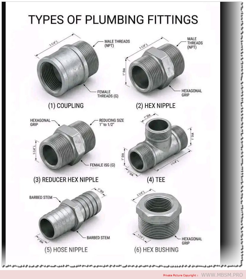
A coupling is used to connect two pipes of the same diameter. It features internal (female) threads on both ends. This is the go-to fitting for extending a straight run of pipe.
2. Hex Nipple
A hex nipple has external (male) threads on both ends. The “hex” refers to the hexagonal section in the middle, which allows a wrench to grip the fitting securely during installation. It is used to connect two female-threaded fittings or valves.
3. Reducer Hex Nipple
Similar to a standard hex nipple, but the two threaded ends are different sizes (e.g., transitioning from a 1″ pipe to a 1/2″ pipe). This allows you to join components of unequal diameters.
4. Tee
A T-shaped fitting with three openings. It is used to split a single line into two separate branches or to combine two lines into one. In the image, this specific tee features male threads on all three ends.
5. Hose Nipple (Barb Fitting)
This fitting is designed to connect a flexible hose to a threaded pipe system.
Barbed Stems: These slide into the hose, and the ridges grip the interior to prevent it from slipping off.
Hex Grip: Used to tighten the fitting into a threaded port.
6. Hex Bushing
A bushing is used to reduce the size of a female threaded opening. It has male threads on the outside and female threads on the inside. You would screw this into a larger port so that a smaller pipe or fitting can be attached to it.
Key Technical Note: Thread Types
The image mentions two common thread standards:
NPT (National Pipe Tapered): Common in North America; the threads are tapered to create a liquid-tight seal.
G (BSP – British Standard Pipe): Common in Europe and internationally; these are parallel threads that usually require a washer or O-ring to seal.
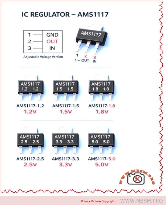
AMS1117 Voltage Regulator
Category: Equipment
written by www.mbsm.pro | 12 April 2026
AMS1117 Voltage Regulator: Common Mistakes, Practical Guide, and Engineering Best Practices
Overview The AMS1117 family of linear voltage regulators (fixed and adjustable versions) is ubiquitous in electronics projects, embedded systems, and power-supply rails. Despite its popularity, technicians and hobbyists repeatedly make the same installation and design mistakes that cause overheating, instability, and premature failure. This article explains those common mistakes, gives engineering‑grade corrections, compares AMS1117 variants with alternatives, and supplies practical tables, values, and installation checklists you can use in a WordPress technical post.
Why AMS1117 Is Widely Used
Simple three‑pin package (GND, OUT, IN) makes board layout straightforward.
Thermal plan: Heatsink area, copper pour, and airflow if W.
Layout: Short traces, wide copper, thermal vias under package for SMD variants.
Protection: Input TVS, series fuse, reverse‑polarity protection.
Testing: Thermal imaging under full load; measure output ripple and transient response.
Thermal Calculation Example
Given: VIN = 12 V, VOUT = 5 V, ILOAD = 0.8 A
Dissipation:
Implication: 5.6 W requires substantial heatsinking; AMS1117 in a TO‑220 or SOT‑223 without heatsink will overheat. Consider switching regulator.
Comparison Table: AMS1117 vs. Common Alternatives
Attribute
AMS1117 (Linear)
LM2596 (Buck)
LDO Modern (e.g., MIC5219)
Efficiency at 5 V out from 12 V in
~42%
~85–95%
~42–60%
Typical max current
~1 A (thermally limited)
3 A (switching)
500 mA–1 A
Output noise
Low‑mid
Higher switching noise
Low
Board complexity
Low
Higher (inductor, diode, caps)
Low
Thermal stress
High for large VIN–VOUT
Low
Moderate
Best use case
Small loads, simple designs
High current, large step‑down
Low‑noise low‑current rails
When to Choose AMS1117 (Use Cases)
Low‑power microcontroller rails (e.g., 3.3 V at < 300 mA).
Simple sensor boards where VIN is close to VOUT (small voltage drop).
Prototyping and low‑volume products where cost and simplicity matter.
When to Avoid AMS1117 (Alternatives)
High current (>1 A) or large VIN–VOUT difference — use a buck converter.
Battery‑powered designs where efficiency is critical — use switching regulator.
Very low noise analog rails — choose a precision LDO with low noise spec.
Layout and PCB Best Practices
Place caps within 2–5 mm of regulator pins.
Use wide input and output traces (or pour copper) to reduce voltage drop and improve heat spreading.
Add thermal vias under SMD packages to move heat to inner or bottom copper.
Keep sensitive analog traces away from the regulator’s hot copper and switching nodes (if present).
Label polarity clearly and include test points for VIN, VOUT, and GND.
Testing and Validation Steps
No‑load test: Verify VOUT with no load; check for oscillation.
Step‑load test: Apply sudden load changes and measure transient response.
Thermal test: Run at maximum expected load for 30 minutes; measure case and PCB temps.
Ripple test: Measure output ripple with oscilloscope; ensure within tolerance for your circuit.
Fault test: Simulate short‑circuit and overvoltage to confirm protection behavior.
Common Failure Modes and Troubleshooting
Symptom: Output drops under load → Check thermal shutdown, insufficient input voltage, or current limit.
Symptom: Output noisy or oscillating → Check output capacitor ESR and placement.
Symptom: Device hot to touch → Check power dissipation calculation and add heatsink or switch to buck converter.
Symptom: No output → Check input presence, reverse polarity protection, and solder joints.
Engineering Notes and Practical Tips
Combine capacitors: a 0.1 µF ceramic in parallel with a 10 µF electrolytic gives best high‑ and low‑frequency performance.
Derate current: assume 70–80% of the absolute max in real designs unless thermal path is proven.
Use thermal simulation or simple hand calculations to size copper pour and heatsink.
Document expected VIN range and include transient protection if VIN can spike (e.g., automotive or industrial environments).
Focus Keyphrase
AMS1117 common mistakes thermal design decoupling capacitor layout oscillation protection buck alternative 1.2V 1.8V 3.3V 5V regulator
SEO Title
Mbsmpro.com, AMS1117 Voltage Regulator, Common Mistakes, Thermal Design, 1.2V–5.0V, Decoupling, Layout, Alternatives
Meta Description
Avoid overheating and instability with AMS1117 regulators. Learn the most common mistakes, thermal calculations, capacitor recommendations, PCB layout tips, and when to choose a buck converter instead.
AMS1117, Voltage Regulator, LDO, Decoupling, Thermal Design, PCB Layout, Buck Converter, 3.3V, 5V, Mbsmgroup, Mbsm.pro, mbsmpro.com, mbsm, Electronics, Power Supply
Excerpt (first 55 words)
AMS1117 linear regulators are simple and cheap, but common mistakes—missing decoupling, poor thermal planning, and long traces—cause instability and overheating. This guide explains capacitor choices, power dissipation math, PCB layout rules, testing steps, and when to switch to a buck converter for efficiency and reliability.
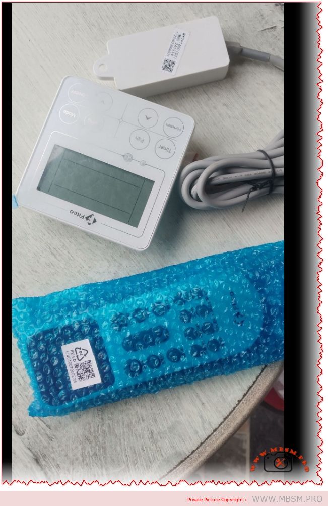
In the world of air conditioning maintenance, control is everything. Whether you are an HVAC technician diagnosing a fault or a homeowner tired of losing the remote, the Fitco Smart Control Kit represents the perfect bridge between reliability and modern technology. This comprehensive system is not just a spare part; it is an upgrade that transforms a standard split system into a smart, fully manageable climate station.
This kit is unique because it offers triple redundancy: a wall-mounted wired thermostat for permanent access, a handheld wireless remote for convenience, and a WiFi module to bridge your cooling system to the cloud. For the artisan bricoleur, this means fewer callbacks for “lost remotes” and easier diagnostics via the wired interface.
Why “Wired” Still Matters in a Wireless World
You might ask, “Why install a wired controller when I have a phone?” The answer is reliability. Wireless signals can fail, batteries die, and phones get lost. A wired controller like the Fitco M+7 Series is hardwired directly to the indoor unit’s PCB. It communicates via a stable data signal (often 0-5V or 12V), ensuring that when you press “Cool,” the compressor engages every time.
Moreover, for commercial applications—like offices or server rooms—a wall-mounted controller prevents employees from losing the remote or setting dangerous temperatures, as many wired units feature “Admin Lock” capabilities.
Technical Specifications & Capabilities
Below is the technical breakdown of the Fitco Control System.
To understand the value of this upgrade, we compare it against standard solutions found in the market.
Criterion
Standard IR Remote
Fitco Hybrid Kit (Wired+WiFi)
Verdict
Reliability
Low (Line of sight required)
High (Direct Wire + Cloud)
Fitco wins for critical cooling.
Placement
Loose / Tabletop
Fixed Wall Mount
Never lose your controller again.
Diagnostics
None (Blind operation)
Error Code Display
Essential for troubleshooting faults.
Smart Features
None
Global App Control
Turn on AC before you arrive home.
Installation
Instant
Requires Wiring
Professional installation recommended.
Tech Note: The inclusion of the WiFi dongle (often a USB or 4-pin header stick) allows the AC to communicate with servers. This means you can integrate your “dumb” AC into Google Home or Amazon Alexa ecosystems without buying a new unit.
Installation Guide: The “Artisan” Approach
Warning: Always disconnect main power before opening the indoor unit.
Locate the PCB Port: Open the front panel of the indoor unit and locate the mainboard. Look for a socket labeled “DISP,” “WIRE_CON,” or “CN40.”
Run the Cable: Fish the shielded 4-core cable from the indoor unit through the wall to the desired thermostat location. Avoid running this parallel to high-voltage (220V) power lines to prevent signal interference.
Mount the Backplate: The Fitco controller separates from its base. Screw the base plate into the wall or switch box.
Connect & Test: Connect the harness. Power up the breaker. The wired controller should light up immediately. If it displays an “E1” or “Communication Error,” check your A/B signal wire polarity.
WiFi Setup: Plug the white Smart Module into the specific USB/Header port on the indoor unit (or the wired controller, depending on model). Scan the QR code to pair with your smartphone.
The “Smart” Advantage: Energy Efficiency
One of the hidden benefits of the Fitco Smart Kit is energy monitoring. Unlike a simple thermostat that just clicks on and off, this intelligent system can often track runtime. By using the “Timer” and “Sleep” algorithms effectively via the app, users typically see a reduction in electricity usage by preventing the AC from running efficiently in empty rooms.
For the refrigeration technician, this kit is a high-value upsell. You are not just repairing an AC; you are modernizing it.
Upgrade your HVAC with the Fitco AC Wired Controller & WiFi Kit. Features dual-interface control, Smart Life app compatibility, and universal split system integration. Perfect for technicians.
Mbsmgroup, Mbsm.pro, mbsmpro.com, mbsm, Fitco Controller, Wired Thermostat, HVAC Smart Kit, Universal AC Remote, WiFi AC Module, Split Air Conditioner, VRF Control, Technician Tools
Excerpt:
The Fitco Wired & Wireless Controller Kit is the ultimate upgrade for any split air conditioning system. Combining the reliability of a hardwired wall thermostat with the convenience of WiFi smart control, this kit ensures you never lose command of your climate. Ideal for offices, homes, and server rooms requiring redundant cooling management.
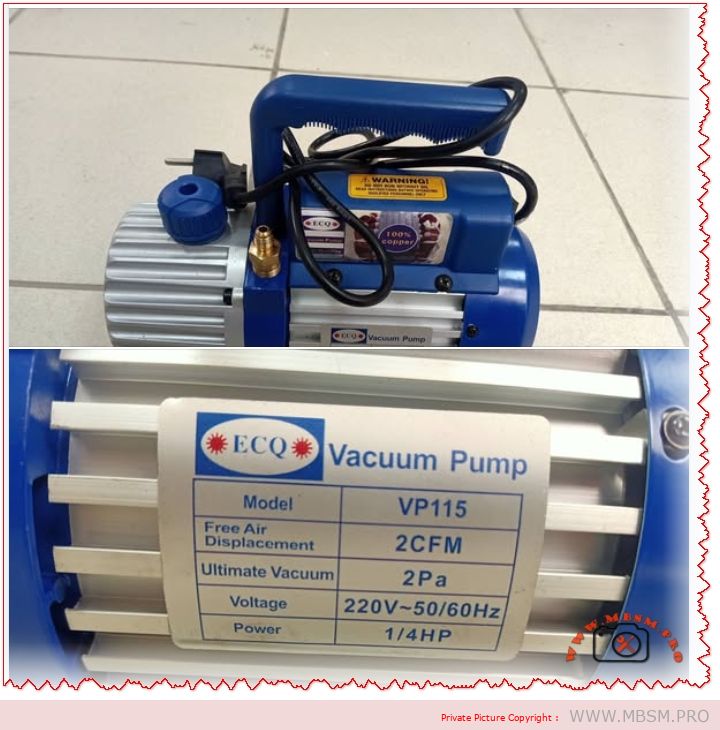
The Unsung Hero of Your Tool Bag: The ECQ VP115 Vacuum Pump
If you work in refrigeration or air conditioning—whether you are fixing a small fridge in a local shop or installing a split system in a new apartment—you know that moisture is the enemy. It is the silent killer of compressors. You can have the best welding skills in the world, but if you leave air inside the pipes, that unit will fail.
This is where the ECQ VP115 comes in. It is not the biggest pump on the market, but for an artisan bricoleur or a technician on the move, it is often exactly what you need. It is compact, it is reliable with its 100% copper winding, and it pulls a vacuum deep enough to degas a system properly before you recharge with R134a or R410a.
Why 2 CFM Matters for Small to Medium Jobs
Many technicians think “bigger is better,” but that isn’t always true. A huge 8 CFM pump is heavy and can actually pull a vacuum too fast on small capillary systems, causing moisture to freeze before it boils off. This 2 CFM (50 L/min) pump is the “Goldilocks” size—perfect for:
Domestic Refrigerators (1/5 HP to 1/3 HP compressors).
Split Air Conditioners (9000 to 18000 BTU).
Car Air Conditioning systems.
It is light enough to carry up a ladder but strong enough to hit 5 Pa (approx 37 microns) of ultimate vacuum.
Technical Specifications: The “Heart” of the Pump
Here is the detailed breakdown of what this machine offers.
Feature
Specification
Model
VP115
Voltage / Frequency
220V~50Hz / 60Hz
Free Air Displacement
2 CFM (approx. 50 L/min)
Ultimate Vacuum
5 Pa (0.05 mBar)
Motor Power
1/4 HP
Motor Type
100% Copper Winding (High durability)
Oil Capacity
320 ml
Intake Fitting
1/4″ Flare (Standard SAE)
Dimensions
275 x 122 x 220 mm
Net Weight
~5.3 kg
Application
R134a, R22, R410a, R407c
Comparison: VP115 (Single Stage) vs. Dual Stage Pumps
When you are deciding between a single-stage pump like this and a more expensive dual-stage unit, it helps to see the difference clearly.
Characteristic
VP115 (Single Stage)
Typical Dual Stage (e.g., 2VP-2)
Verdict
Vacuum Depth
5 Pa (Good)
0.3 Pa (Excellent)
Single stage is fine for standard repairs; Dual is for deep-freeze/scientific work.
Weight
~5 kg (Light)
~10 kg (Heavy)
VP115 is much easier to carry to rooftops.
Price
Affordable
Expensive
VP115 offers better ROI for general repairs.
Maintenance
Simple Oil Change
Complex
Single stage is more forgiving with dirty oil.
Performance Analysis: Speed vs. Quality
Let’s compare how this pump performs against other common sizes when evacuating a standard 12,000 BTU Split AC.
Pump Size
Time to 500 Microns
Risk of Freezing Moisture
Best Use Case
1 CFM (Small)
45+ Minutes
Low
Very small fridges only.
2 CFM (VP115)
20-25 Minutes
Balanced
Residential AC & Fridges.
6 CFM (Large)
5-8 Minutes
High (if not careful)
Commercial chillers / Large VRF.
Pro Tip: Always use a micron gauge. The sound of the pump changing pitch is a good sign, but it is not a measurement!
Maintenance & Troubleshooting
To keep your VP115 running for years, follow this simple maintenance schedule.
Symptom
Probable Cause
Solution
Poor Vacuum
Dirty or low oil
Drain oil while warm and refill with fresh vacuum oil.
Oil Mist at Exhaust
Normal operation
This is normal when pumping large amounts of air at the start.
Pump Overheating
Low voltage or blocked fan
Check your extension cord gauge and clean the fan cover.
Hard Start
Cold weather
Warm up the oil or open the inlet port briefly to relieve pressure.
Discover the ECQ Vacuum Pump VP115 (2 CFM, 1/4 HP). Perfect for HVAC technicians and artisans. Full specs, maintenance tips, and comparisons for R134a/R410a systems.
The ECQ Vacuum Pump VP115 is the ideal tool for the artisan bricoleur. With 2 CFM displacement and a durable 1/4 HP motor, it perfectly balances portability and power for residential AC and fridge repairs. This guide covers specifications, maintenance, and why 100% copper winding matters for your daily work.
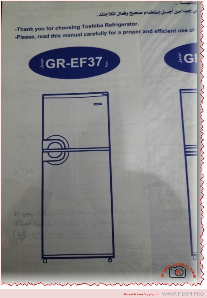
SEO Title (60 characters max): “Toshiba GR-EF37 350L No-Frost Refrigerator | A-Class Energy Efficient”
Meta Description (160 characters max): “Discover the Toshiba GR-EF37 350L no-frost refrigerator with platinum deodorizer, eco-friendly R600a refrigerant, and 10-year compressor warranty. Perfect for large families.”
Excerpt (55 words): “The Toshiba GR-EF37 is a premium 350-liter no-frost refrigerator featuring advanced cooling technology, platinum deodorizer filtration, and exceptional energy efficiency. With dual cooling zones, R600a eco-friendly refrigerant, and a 10-year compressor warranty, this 2-door model represents excellent value for large households seeking reliable refrigeration.”
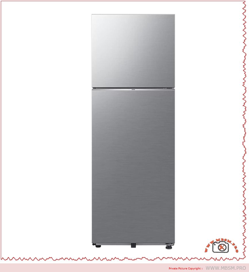
Understanding the Toshiba GR-EF37: A Premium No-Frost Cooling Solution
The Toshiba GR-EF37 stands as one of the market’s most thoughtfully engineered refrigerators for medium to large households. This 350-liter capacity model combines no-frost convenience with exceptional energy efficiency, making it an intelligent choice for families prioritizing both performance and sustainability. The refrigerator has gained particular recognition in Middle Eastern and North African markets due to its reliability and advanced cooling architecture.
What distinguishes the GR-EF37 from conventional refrigeration units is its seamless integration of multiple proprietary technologies designed to preserve food freshness while minimizing operational costs. Unlike traditional refrigerators requiring periodic manual defrosting, this model employs automatic no-frost technology that continuously circulates cold air without ice accumulation, fundamentally transforming the refrigeration experience.
Physical Specifications and Dimensional Overview
The GR-EF37 occupies moderate kitchen space while delivering substantial storage capacity. Understanding these dimensions helps determine kitchen compatibility before purchase:
Specification
Measurement
Details
Total Capacity
350 Liters
Ideal for families of 5-7 members
Width
604 mm (60.4 cm)
Standard kitchen doorway compatible
Depth
681 mm (68.1 cm)
Fits typical kitchen alcoves
Height
1723 mm (172.3 cm)
Eye-level freezer compartment access
Net Weight
64 kg
Requires stable flooring; move with dolly
Gross Weight
71 kg
Includes packaging for transport
Vegetable Drawer
19.3 Liters
Dedicated crisper capacity
Number of Doors
2 Doors
Top freezer, bottom refrigerator layout
Warranty
10 Years (Compressor)
Industry-leading coverage period
These dimensions closely align with competitors like the Samsung RT38DG5A2BBXHL (63 × 173 × 73 cm), demonstrating the GR-EF37’s efficient space utilization without sacrificing capacity.
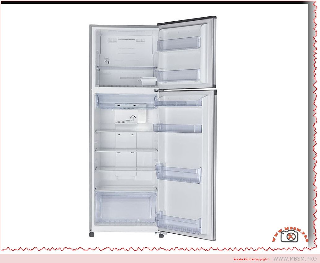
The no-frost cooling system represents a revolutionary advancement in domestic refrigeration. Rather than allowing ice to accumulate naturally inside the freezer compartment, the Toshiba GR-EF37 employs a fan-assisted circulation mechanism that continuously disperses dehumidified cold air throughout both refrigerator and freezer sections.
How the System Functions:
Traditional frost-accumulating refrigerators experience moisture entering through door openings and from stored food items. This moisture freezes on evaporator coils, progressively reducing cooling efficiency. The GR-EF37 eliminates this problem through compartmentalized evaporator placement and intelligent air routing.
Measurable Performance Advantages:
Research conducted on no-frost refrigeration systems demonstrates significant efficiency improvements. A study comparing thermal performance indicators revealed that no-frost systems maintain 15-20% more consistent temperatures compared to direct-cool alternatives. For food preservation, this consistency proves critical—it prevents fluctuating conditions that accelerate spoilage and reduces freezer burn incidents by up to 40% according to domestic refrigeration analysis.
The system automatically defrosts evaporator coils during compressor idle cycles, directing melted water through drain channels rather than into food storage areas. This automatic defrosting occurs without user intervention, eliminating the inconvenience of removing frozen goods and waiting for ice to thaw—a process that previously consumed 4-6 hours monthly for traditional units.
Energy Efficiency: Understanding the A-Class Rating
The Toshiba GR-EF37 carries the Energy Efficiency Class A designation, representing the highest performance tier in modern appliance ratings. This classification indicates the unit consumes significantly less electricity than comparable capacity refrigerators.
Energy Performance Benchmarking:
Factor
Class A Performance
Class B Comparison
Class C Comparison
Annual Energy Consumption
~320-370 kWh
~420-480 kWh
~520-600 kWh
Monthly Cost (@ $0.12/kWh)
~$3.20-$3.70
~$4.20-$4.80
~$5.20-$6.00
Annual Savings vs Class B
~20-25% less
Baseline
Higher consumption
Monthly Operational Cost
Lowest tier
30% higher
50-60% higher
The Class A rating becomes particularly valuable in regions with high electricity costs. Over a 10-year product lifespan, this efficiency differential translates to approximately $800-1,200 in cumulative energy savings compared to Class B alternatives, effectively subsidizing a significant portion of the refrigerator’s purchase price.
This performance stems directly from the GR-EF37’s inverter-based compressor, which modulates cooling intensity based on internal temperature fluctuations rather than operating at constant capacity. During periods of minimal temperature variance, the compressor reduces power draw substantially, whereas traditional fixed-speed compressors maintain maximum operation regardless of cooling demand.
R600a Refrigerant: Environmental and Performance Advantages
The Toshiba GR-EF37 utilizes R600a (isobutane) refrigerant, an environmentally superior choice compared to the R134a refrigerant used in many competing models. This technical distinction carries both environmental and operational implications.
Researchers analyzing R600a performance in domestic refrigerators observed that “the coefficient of performance was found to be in the higher range compared to R134a, almost 20%-25% better than R134a at constant load conditions.” The practical implication: the GR-EF37 cools food more rapidly while consuming less electrical energy, representing genuine thermodynamic superiority rather than incremental improvement.
Environmental Impact Significance:
R600a carries negligible global warming potential (GWP of 3-4 versus R134a’s 1,450), making it climatically preferable despite being hydrocarbon-based. Modern compressors designed for R600a incorporate precision engineering that safely contains the refrigerant, and decades of Asian-market deployment demonstrates reliable safety profiles. The GR-EF37’s manufacturing process utilizes cyclopentane foam insulation rather than CFC-based alternatives, further minimizing the unit’s environmental footprint.
Design Features: Platinum Deodorizer and Interior Architecture
The GR-EF37 incorporates specialized features addressing common refrigeration challenges that impact daily user experience:
Platinum Deodorizer Filter System:
This proprietary filtration mechanism neutralizes odor molecules through activated carbon enriched with platinum compounds. Unlike basic carbon filters requiring quarterly replacement, the platinum formulation extends operational life to 12-18 months while providing superior odor capture across diverse food categories. The filter addresses cross-contamination issues inherent in shared cooling spaces—onion scent no longer permeates dairy products, and strong spices remain compartmentalized.
Interior Shelving and Food Organization:
Hardy glass shelves with reinforced tempering technology support up to 150kg distributed weight, enabling storage of bulk purchases and large containers without deformation. The gentle slopes prevent liquid spillage from flowing toward door-mounted compartments, and the translucent construction permits rapid visual inventory assessment without opening doors—reducing cold air loss and maintaining energy efficiency.
Vegetable and Fruit Preservation Drawer:
The dedicated 19.3-liter crisper drawer maintains enhanced humidity levels optimal for produce storage, extending vegetable freshness by 5-7 days compared to standard refrigerator sections. Humidity control prevents moisture loss that causes wilting while avoiding condensation that promotes bacterial growth.
Comparative Market Analysis: How the GR-EF37 Positions Against Competitors
Understanding the GR-EF37’s competitive positioning provides context for purchase decisions:
Toshiba GR-EF37 vs. Samsung RT38DG5A2BBXHL (350L 2-Star):
Attribute
Toshiba GR-EF37
Samsung RT38DG5A2BBXHL
Winner/Comment
Energy Class
A (Superior)
2-Star (~Class B equivalent)
Toshiba: 20-25% more efficient
Annual Energy Cost
~$38-45
~$50-60
Toshiba saves $120-150/year
Compressor Warranty
10 Years
10 Years
Equal coverage
Standard Warranty
1 Year implied
1 Year
Equivalent
Smart Features
Basic controls
Wi-Fi SmartThings enabled
Samsung offers connectivity
Cooling Technology
No-Frost (Automatic)
Twin Cooling Plus (Auto)
Both prevent manual defrosting
Dimensions
604×681×1723mm
630×732×1780mm
Toshiba slightly more compact
Price Point
Mid-range (~$400-500)
Premium (~$600-800)
Toshiba offers better value
Best For
Budget-conscious buyers
Tech-integrated smart homes
Different use cases
The Samsung model appeals to users prioritizing IoT integration and smartphone connectivity, while the Toshiba serves cost-conscious buyers seeking reliability and energy economy.
Toshiba GR-EF37 vs. LG Refrigerators (350L Category):
LG’s competing models like the GL-T502FRS2 emphasize multi-air flow systems and premium finish options but typically carry higher energy classifications (2-3 Star ratings) and reduced warranty coverage compared to the GR-EF37’s 10-year compressor protection. For users prioritizing longevity and operational economy over smart-home integration, the Toshiba represents superior total-cost-of-ownership value.
Installation and Operational Considerations
Proper Placement Fundamentals:
The GR-EF37 requires minimum 10cm clearance on both sides and rear to permit adequate heat dissipation from compressor-mounted condenser coils. Placement adjacent to ovens or direct sunlight significantly reduces efficiency and increases compressor cycling frequency. Optimal locations feature ambient temperatures between 10°C-32°C; tropical climates require ensuring air-conditioning maintains surrounding temperature within this range.
Electrical Requirements:
The unit operates on standard 220-240V AC, 50Hz power supply common in Middle Eastern and European markets. Stabilizer-free operation is supported (confirmed stabilizer-free on competitive models), though voltage stabilizers remain recommended in regions experiencing fluctuations exceeding ±10V. A dedicated circuit prevents voltage sags that could damage compressor motor windings.
First-Time Operation Protocol:
Upon delivery, allow the unit to stand upright for minimum 4-6 hours before initial power connection. This permits refrigerant redistribution in the sealed system after potential tilting during transport. Clean interior surfaces with mild soap solution before loading food items.
Monthly: Inspect door seals for gaps; wipe rubber gaskets with mild detergent to prevent mold growth
Quarterly: Clean condenser coils located beneath or behind unit using brush; debris restricts heat dissipation
Semi-Annual: Defrost and clean interior crisper drawers; remove platinum deodorizer filter and rinse under running water
Annual: Check temperature using independent thermometer in both compartments; adjust controls if readings deviate >2°C
Troubleshooting Common Issues:
Should the compressor run continuously without reaching set temperature, verify that door seals close completely (misalignment reduces cooling efficiency by 15-30%). If frost accumulates despite no-frost technology, the automatic defrost timer may require service—contact authorized Toshiba technicians rather than attempting internal repairs that could breach system integrity.
Professional Recommendations and Conclusion
The Toshiba GR-EF37 represents a mature refrigeration solution balancing energy efficiency, environmental responsibility, and practical user functionality. Its 10-year compressor warranty signals manufacturer confidence in long-term reliability, while the Class A energy rating ensures operational costs remain economically favorable across extended product lifespan.
This model suits buyers seeking:
Maximum energy economy in mid-capacity refrigeration
Environmentally conscious appliance selection
Proven reliability over cutting-edge smart features
Strong warranty protection and manufacturer support
For regions throughout North Africa, the Middle East, and countries utilizing 220-240V/50Hz electrical standards, the GR-EF37 delivers consistent value and performance. Its no-frost architecture eliminates refrigeration’s most persistent inconvenience—manual defrosting—while R600a refrigerant technology provides thermodynamic advantages that mainstream manufacturers continue adopting as environmental regulations tighten globally.
Investment in this refrigerator represents commitment to both household food safety and responsible resource consumption, delivering measurable energy savings that accumulate meaningfully across the unit’s intended 12-15 year operational lifespan.
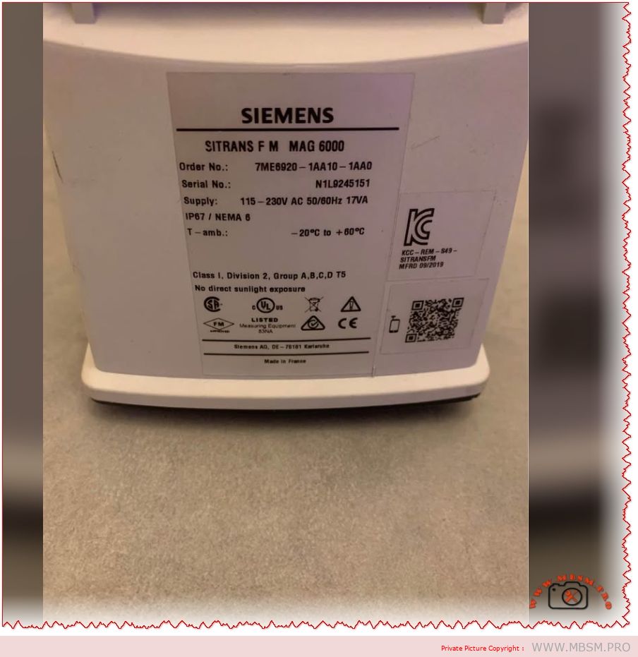
Mbsmpro.com, Flowmeter Transmitter, Siemens SITRANS FM MAG 6000, 7ME6920‑1AA10‑1AA0, 115‑230V AC 50/60Hz, IP67 / NEMA 6, Class I Div.2, Batch Control, High‑Accuracy Electromagnetic Flow Measurement
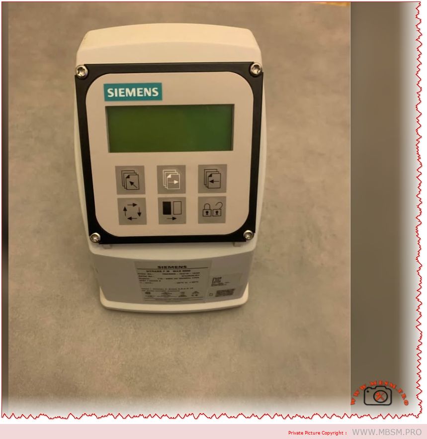
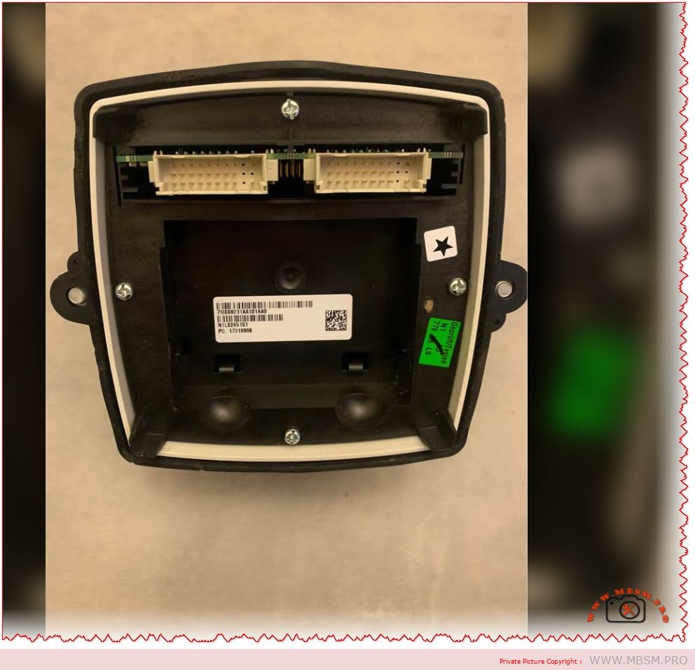
Overview of the Siemens SITRANS FM MAG 6000 7ME6920‑1AA10‑1AA0
The Siemens SITRANS FM MAG 6000 with order number 7ME6920‑1AA10‑1AA0 is a microprocessor‑based electromagnetic flow transmitter engineered for high‑accuracy liquid measurement in industrial applications. It combines IP67 / NEMA 6 protection, a back‑lit alphanumeric display, and wide‑range 115‑230 V AC 50/60 Hz supply for compact or wall‑mount installations in harsh environments.
Technical specifications and ratings
The table below summarizes the key technical data of the SITRANS FM MAG 6000 transmitter variant 7ME6920‑1AA10‑1AA0.
Specification
Value
Comment
Product family
SITRANS FM MAG 6000
Electromagnetic flow transmitter.
Order No.
7ME6920‑1AA10‑1AA0
IP67, compact / wall‑mount version.
Supply voltage
115–230 V AC, 50/60 Hz
Switched‑mode power supply.
Enclosure
IP67 / NEMA 6, polyamide reinforced with glass fiber
Suitable for wash‑down and outdoor use.
Ambient temperature
−20 °C to +60 °C
For display version.
Measurement accuracy
±0.2% of flow rate ±1 mm/s (with sensor)
High‑precision metering.
Output functions
Analog, pulse/frequency, relay outputs
For flow rate, direction, alarms, limits.
Diagnostics
Comprehensive self‑diagnostics and error logging
Supports maintenance and troubleshooting.
Approvals
FM/CSA Class I Div.2 Groups A,B,C,D T5 and others
For hazardous areas (certain configurations).
These characteristics make the SITRANS FM MAG 6000 transmitter a solid choice wherever reliable and repeatable volumetric flow measurement is required, from water distribution networks to process industry batching lines.
Functional features and exploitation in industrial systems
The MAG 6000 platform offers several core functions that go beyond basic flow indication.
Instantaneous flow rate and totalizers: Two independent totalizers allow separate registration of forward and reverse flow or batching totals.
Wide turndown and low‑flow cut‑off: Digital signal processing and high‑resolution measurement provide stable readings at both very low and very high velocities.
Batch control and limit switching: Integrated batch controller with configurable relay outputs can start, stop, and fine‑tune dosing operations without an external PLC in smaller systems.
Diagnostic and self‑verification: Built‑in self‑diagnostics and optional verification functions help operators detect coil faults, empty pipe alarms, configuration errors, and sensor problems early.
In daily exploitation this means a plant can use a single MAG 6000 transmitter as a measurement, supervisory, and basic control element, saving cabinet space and engineering time while maintaining metering‑class accuracy.
Comparison with other MAG transmitters and typical competitors
To clarify the position of the MAG 6000, the table compares it with the Siemens MAG 5000 transmitter and a generic compact electromagnetic flow transmitter of similar class.
Feature
SITRANS FM MAG 6000
Siemens MAG 5000
Typical compact magmeter transmitter
Accuracy
±0.2% of flow rate ±1 mm/s
±0.4% of flow rate ±1 mm/s
Often ±0.5–1.0% of flow rate
Power supply options
12–24 V AC/DC or 115–230 V AC 50/60 Hz
12–24 V AC/DC or 115–230 V AC
Usually one fixed range (e.g. 100–240 V AC)
Enclosure rating
IP67 / NEMA 4X/6 and IP20 (19’’ insert)
IP67 / NEMA 6 and IP20
Often IP65 only
Functions
Batch control, advanced diagnostics, plug‑in communication modules
Basic flow and totalizers, limited advanced functions
Basic flow indication and 4–20 mA output
Typical application
Custody‑transfer, demanding industrial processes, water utilities
Standard industrial water and wastewater
Simple plant utilities and OEM skids
Compared with the MAG 5000, the MAG 6000 offers tighter accuracy, extended communication options, and integrated batch functionality, making it more suitable for high‑value products and billing applications. Against a typical compact magmeter, the MAG 6000 stands out with its rugged IP67 housing, richer diagnostics, and modular communications, which are important in large plants seeking long‑term reliability and easy integration.
Value comparison with alternative technologies
When deciding between the SITRANS FM MAG 6000 and other flow measurement technologies, engineers usually compare performance, installation constraints, and lifecycle cost.
Criterion
MAG 6000 + electromagnetic sensor
Turbine flowmeter
Differential‑pressure (orifice) system
Moving parts
None, fully static measurement
Rotating turbine prone to wear
No moving parts but involves impulse lines
Accuracy and stability
High accuracy (±0.2%) with very low drift
Good initially, but degrades with wear
Moderate; affected by installation and density changes
Sensitivity to fluid properties
Largely independent of pressure, temperature, and viscosity if fluid is conductive
Sensitive to viscosity, density, and contamination
Requires stable density and Reynolds number
Maintenance
Minimal; occasional cleaning and verification
Regular bearing replacement and cleaning
Periodic transmitter recalibration and impulse line purging
Typical media
Water, wastewater, slurries, chemicals with sufficient conductivity
Clean liquids
Gases, steam, some liquids
Because the electromagnetic principle does not introduce obstruction or moving parts, the MAG 6000 solution usually offers lower total cost of ownership in water and wastewater plants compared with turbine or orifice systems, especially where solids or scaling are present.
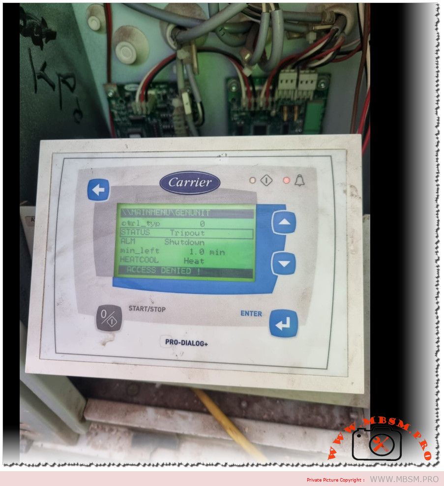
Carrier Pro-Dialog+ Tripout shutdown: how the controller protects HVAC equipment
Modern Carrier Pro-Dialog+ controllers are designed to stop a chiller or rooftop unit whenever operating limits are exceeded, displaying a Tripout status and Shutdown alarm to prevent serious damage. This behaviour can seem abrupt to building owners, but for technicians it is a valuable diagnostic signal that the safety chain has done its job.
Main controller messages
The Pro-Dialog+ interface provides a structured view of the unit’s operating state and alarms.
STATUS = Tripout means the unit has reached a fault shutdown condition and is fully locked out until the fault is cleared and the controller is reset.
ALM = Shutdown indicates that the controller has issued a complete stop order because one or more safety inputs have changed state.
Other fields, such as min_left (minimum time left before restart) and HEAT/COOL mode, indicate how long the unit must remain stopped and which operating mode was requested when the alarm occurred. If the user tries to enter restricted menus without the proper password, the display shows ACCESS DENIED, confirming that configuration-level parameters are protected.
Typical causes of Tripout
Tripout and Shutdown are linked to a well‑defined list of protective functions in Carrier’s documentation.
Common triggers include high‑pressure cut‑out, low‑pressure or loss of refrigerant, water or air flow loss, pump failure, motor overloads, or anti‑freeze protection on the evaporator.
The controller monitors digital inputs and analogue sensors; if a safety contact opens while the unit is commanded to run, it records an alarm, stops the circuit, and may require a manual reset.
For example, if the evaporator pump feedback contact opens after a start command, the Pro-Dialog logic raises a pump failure alarm and blocks any new start until a technician has verified the hydraulic circuit. This strict logic reduces the risk of running a compressor with no flow, a situation that can quickly lead to overheating and mechanical failure.
Access levels and password protection
Carrier’s manuals emphasise that configuration changes are reserved for authorised personnel using password‑protected menus.
Users can navigate status, inputs, outputs, and alarm history, but changes to setpoints, safety delays, or configuration tables require entering a correct password.
If a password is entered when the unit is not fully stopped, the message ACCES dEniEd appears, preventing unsafe modifications while the machine is running.
This hierarchy of access levels protects the integrity of safety parameters and ensures that only trained technicians adjust critical values such as start‑up delays or capacity control settings. For service companies like Mbsmgroup, documenting passwords and authorised changes forms a key part of professional maintenance records and quality assurance.
Troubleshooting workflow for technicians
A structured workflow helps technicians move from the Tripout message to a reliable repair.
First, review the ALARMS and ALARMS HISTORY menus to identify which safety triggered the fault shutdown and whether it is recurrent.
Next, inspect the relevant circuit: verify water or air flow, check pump or fan operation, inspect fuses and overloads, and measure system pressures and temperatures against manual values.
Once the root cause is identified and corrected—for example, resetting a tripped overload, cleaning a clogged filter, or restoring proper flow—the technician can reset the alarm at the controller and observe a full operating cycle. Experienced teams often cross‑check field readings with Carrier’s troubleshooting charts to confirm that operating conditions remain within the recommended envelope after restart.
Reference data table for Pro-Dialog+ Tripout
The following table summarises key concepts technicians use when analysing a Tripout situation on Carrier Pro-Dialog and Pro-Dialog+ controlled units.
Item
Description
Practical role in diagnosis
Tripout status
Fault shutdown condition in which the unit is locked out until reset.
Confirms that a safety event has occurred and that automatic restart is blocked.
Shutdown alarm
Alarm state where the controller stops the unit due to one or more active faults.
Guides the technician to consult alarm menus and history before attempting a restart.
Safety inputs
Digital contacts for HP, LP, flow switches, overloads, freeze stats and interlocks.
Identifies which protective loop opened and where to begin physical inspection.
Alarm history menu
Pro-Dialog function that stores a list of previous alarms and operating states.
Helps determine whether the Tripout is isolated or part of a recurring pattern.
Access denied message
Display text when a user without sufficient rights attempts to enter protected settings or when password rules are not met.
Prevents accidental or unsafe adjustments and signals need for authorised access.
Manual reset procedure
Sequence of acknowledging alarms and resetting the controller once the fault is corrected.
Restores operation while ensuring that the underlying problem has been solved.
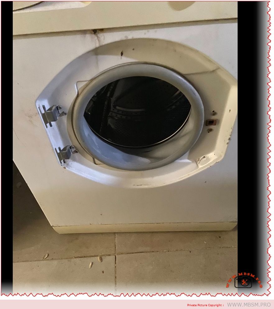
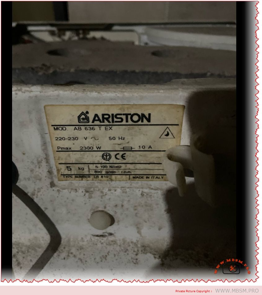
Ariston AB 636 T EX: Technical Identification Plate Guide for Repair and Maintenance
Overview of the Ariston AB 636 T EX Plate
The image shows the rating plate of an Ariston AB 636 T EX front‑loading washing machine, a classic European model widely sold in the late 1990s and early 2000s. This metal label concentrates the essential electrical and mechanical data needed for correct installation, troubleshooting, and ordering spare parts.
Decoding the Electrical Specifications
The plate confirms that the machine operates on 220–230 V, 50 Hz single‑phase power, drawing a maximum power of 2300 W and a nominal current of 10 A. These values indicate that the washer is designed for typical European domestic circuits and must be connected to a properly grounded outlet protected by a 10–16 A breaker.
Technicians use the Pmax 2300 W figure to size wiring, check energy consumption, and verify heater and motor performance during diagnostics. Overheating, tripped breakers, or burned connectors often result from ignoring these limits during installation or repair.
Mechanical Data and Pressure Switch Range
On the lower part of the label, the plate lists maximum load 5 kg and a spin speed of about 600 rpm, which class the AB 636 T EX as an entry‑level to mid‑range washer by today’s standards. This moderate spin speed explains why these machines often require longer drying times compared with newer 1000–1400 rpm units.
The marking 5–100 N/cm² refers to the water pressure range for the pressure switch and hydraulic system, compatible with standard domestic water supplies. Maintaining this range is crucial for correct filling, level detection, and safe operation of the heating element.
Why the Rating Plate Matters for Technicians
For repair professionals and advanced DIY users, the rating plate is the identity card of the washing machine. It provides the exact model (AB 636 T EX) and type number LB 610, data that spare‑parts catalogues and service manuals use to match compatible components. Without these references, ordering parts like bearings (6203‑2Z), pressure switches, or door locks risks costly mistakes.
The “Made in Italy” indication helps trace manufacturing standards and sometimes the availability of regional variants sharing similar mechanical parts but different decorative panels or program boards.
Key Technical Data Table
Parameter
Value on Plate
Practical Use in Service
Supply voltage
220–230 V, 50 Hz
Verifies compatibility with local mains and UPS/inverter use.
Maximum power (Pmax)
2300 W
Used to size wiring, breakers, and estimate energy draw.
Nominal current
10 A
Confirms circuit protection rating and plug type.
Maximum load washing machine
5 kg
Helps avoid overloading and drum/bearing damage.
Spin speed
Approx. 600 rpm
Indicates residual moisture and cycle performance.
Water‑pressure range
5–100 N/cm² (pressure switch)
Guides diagnostics for fill and level faults.
Type / code
AB 636 T EX – Type LB 610
Essential for parts catalogues and service documentation.
Useful Resources: Images and Documentation
Several specialised websites still provide visual references and spare‑parts diagrams for the AB 636 T EX. High‑resolution product photos and exploded views can help confirm component positions before disassembly. These resources are particularly useful when documenting repairs or creating training content on platforms such as Mbsmgroup and Mbsm.pro.
For deeper technical information, technicians can consult multi‑page PDF manuals and parts lists for the Ariston AB 636 T family, which cover installation, wiring diagrams, and troubleshooting charts. Such documents detail bearing codes, seal dimensions, and pressure‑switch compatibility for AB 636 T EX and its derivatives.
LG T1387NEHVE 13.2 kg Smart Inverter, Washing Machine
Category: Equipment
written by www.mbsm.pro | 12 April 2026
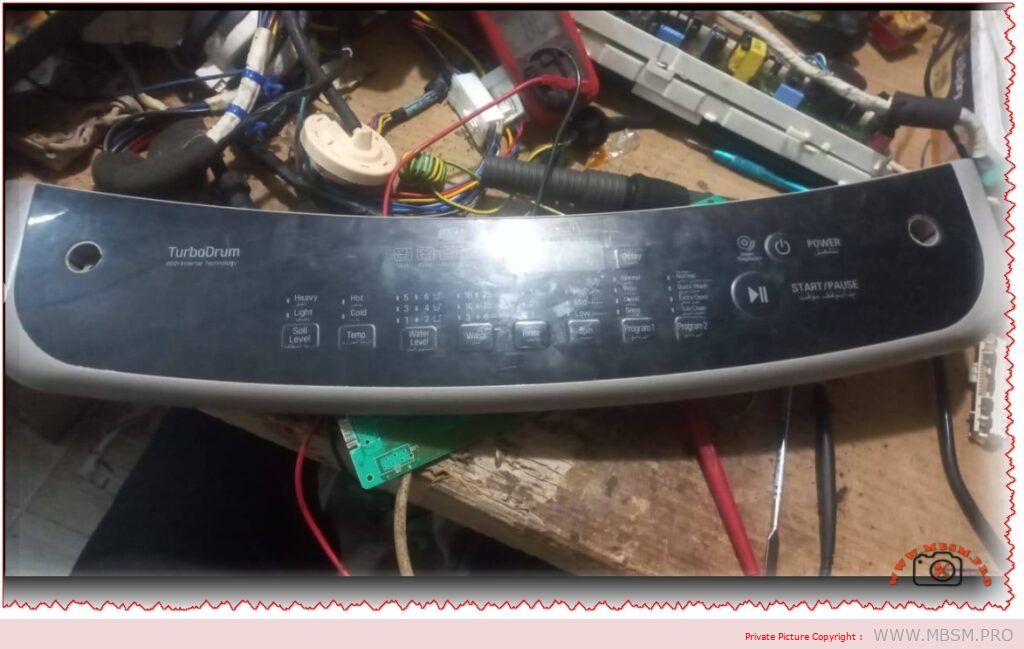
LG T1387NEHVE 13.2 kg Smart Inverter Top Load Washing Machine Nameplate: What Every Technician Should Read
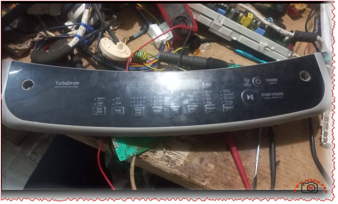
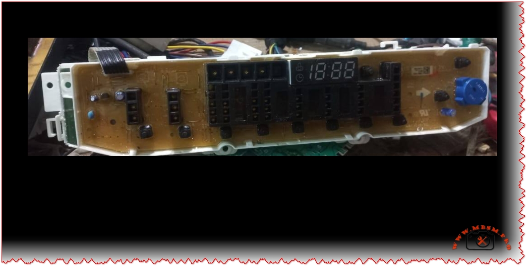
The label fixed to the side of the LG T1387NEHVE washing machine is more than a simple sticker; it is a compact technical identity card that tells you exactly what this appliance can do, how it should be powered, and when it was manufactured. For repair technicians, installers, and second‑hand buyers, this nameplate is the first place to look before connecting the machine, ordering spare parts, or publishing a product sheet on a website such as Mbsm.pro or Mbsmgroup.
Technical identity of the LG T1387NEHVE
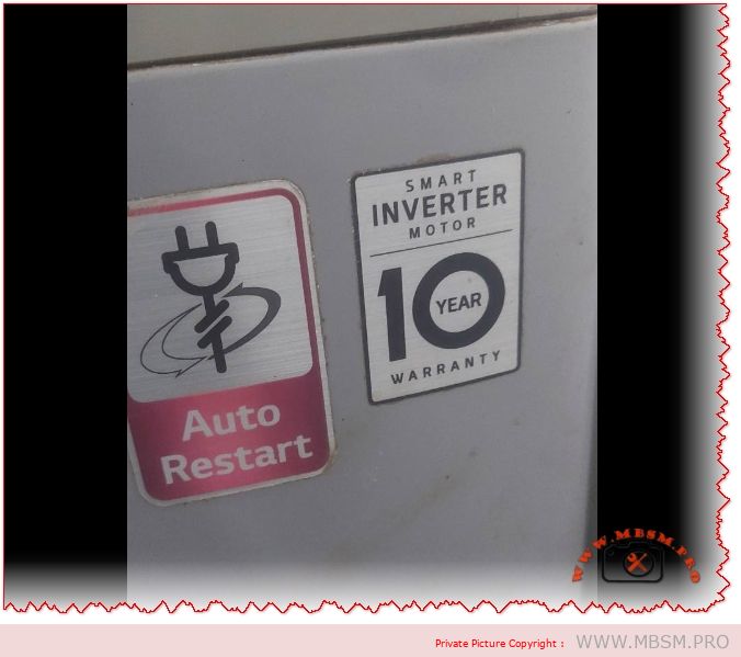
The image shows a white identification label on a silver cabinet with the LG logo followed by the description Fully Automatic Washing Machine and the model code T1387NEHVE. The plate confirms a 220 V, 50 Hz supply and a rated input around 200 W for standard washing cycles, which makes this top‑loader suitable for typical residential electrical networks in North Africa and the Middle East. The capacity printed on the label is 13.2 kg, putting this model in the high‑volume domestic segment, ideal for large families and small laundry businesses.
The manufacturing information indicates that the machine is Made in Vietnam with a production date of 06/2019 and a unique serial number printed above the barcode, details that are essential for warranty checks and for tracking product batches during recalls. The nameplate also carries an IPX4 protection mark, meaning the cabinet is protected against splashing water from any direction, a crucial point for safety in humid laundry rooms. Next to the compliance icons, the product code format (like 1S88NEHVE.ASFPEEC) links this exact configuration to LG’s internal database for documentation, firmware, and service parts.
Main specifications and dimensions
Behind this modest label there is a full‑size 13.2 kg smart inverter top‑load washer with modern LG technology. Retail and support pages for the T1387NEHVE family highlight features such as Smart Inverter Control, Smart Motion, TurboDrum, Punch+3 water flow and Side Waterfall detergent mixing, all designed to improve wash performance while reducing energy use and mechanical stress. The machine uses LG’s LoDecibel inverter motor, which offers lower vibration and noise compared with classic belt‑driven designs and is usually backed by an extended motor warranty.
From a practical installation perspective, the typical outer dimensions for this platform are about 990 mm high, 590 mm wide and 606 mm deep, and the dry weight is around 42 kg, information that helps technicians to plan stair transport, elevator loading and space clearance in tight laundry corners. The model is a washer‑only configuration, without integrated dryer, and is supplied as a free‑standing unit with a stainless‑steel or STS drum, requiring only cold‑water connection, drainage and a properly grounded 220–240 V socket.
Why the nameplate matters for service and resale
For field technicians, reading the nameplate before any intervention is a basic but critical habit. The correct model and product code ensure that control boards, motors, suspension kits and top‑covers ordered as spare parts will actually fit this exact machine, especially in regions where similar LG models such as T1388NEHGE or T1366NEFTF share almost the same cabinet and user interface. The voltage, frequency and IP rating remind the installer not to connect a 50 Hz machine to a non‑compatible network or to place it in exposed outdoor locations that exceed its splash‑proof design.
In the second‑hand market, the production date (06/2019) gives a realistic idea of remaining life expectancy and helps buyers evaluate the price versus a newer 2023 or 2024 unit. Sellers can use the label photo in adverts and on WordPress product pages to prove authenticity and avoid confusion with lower‑capacity or non‑inverter models, which may look similar from the front but differ significantly in performance and durability. For online catalogues like Mbsmgroup and mbsmpro.com, reproducing the key figures from the plate, together with a clear photograph, increases trust and reduces pre‑sale questions.
Specification table for WordPress article
Item
Value
Model name
LG T1387NEHVE top load fully automatic washer.
Washing capacity
13.2 kg laundry load.
Power supply
220–240 V, 50 Hz single‑phase.
Rated input (wash)
Around 200 W according to the label in the image.
Motor type
Smart Inverter motor with LoDecibel quiet system.
Wash technologies
Smart Motion, TurboDrum, Punch+3, Side Waterfall, Auto Pre‑Wash.
Drum material
Stainless‑steel (STS) top‑loading drum.
Dimensions (H × W × D)
Approx. 990 × 590 × 606 mm.
Net weight
About 42 kg.
Protection rating
IPX4 splash‑proof cabinet (from nameplate).
Country of manufacture
Vietnam, production date 06/2019.
Product / code family
T1387NEHVE.ASFPEEC – belongs to LG 13–13.2 kg smart inverter series.
Useful image and PDF resources for your article
For a richer WordPress article, you can safely embed or link to a few illustrative media and documents related to this LG top‑load platform:
High‑resolution product photos of LG smart inverter top‑load washers in the same family (13 kg class) are available on LG regional sites; for example the official gallery for similar 13 kg top‑load models such as the T1366NEFTF shows clear cabinet, control panel and drum views.
Detailed commercial images and lifestyle shots of a 13–13.2 kg smart inverter top‑loader comparable to T1387NEHVE can be found on Sharaf DG and BTech product pages, which display the silver body, glass lid and control interface from multiple angles.
For technical documentation and catalog PDF links you can add to your post:
LG’s support portal for the T1387NEHVE series provides user manuals and sometimes quick‑start guides under similar codes like T1388NEHVE; the manual hosted on Manua.ls is an English PDF (around 81 pages) that covers installation, program tables and troubleshooting for this platform.
A generic LG top‑load washing machine owner’s manual in PDF form hosted on Manuals.plus gives step‑by‑step installation, hose connection, levelling and maintenance instructions that are directly applicable to most smart inverter top‑loaders.
Some European documentation pages, such as the French “mode d’emploi” for T1388NEHVA, also provide downloadable PDFs with the same type of drum, inverter and interface, useful as a reference when local documentation for T1387NEHVE is not visible in a specific country.
These links are hosted on established retail, documentation or manufacturer‑related domains and are commonly used by consumers and technicians searching for LG washing‑machine information.
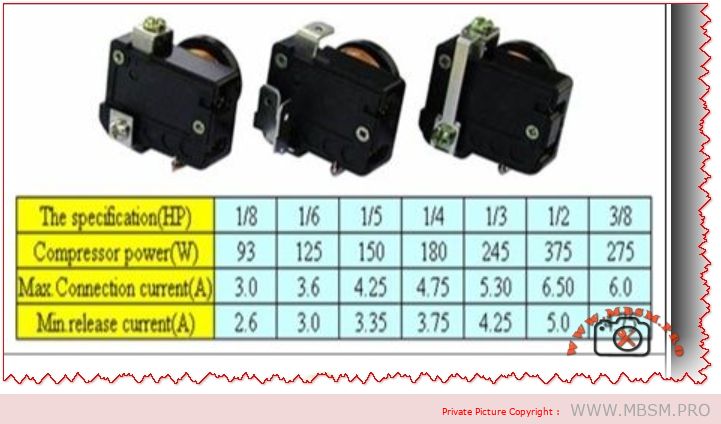
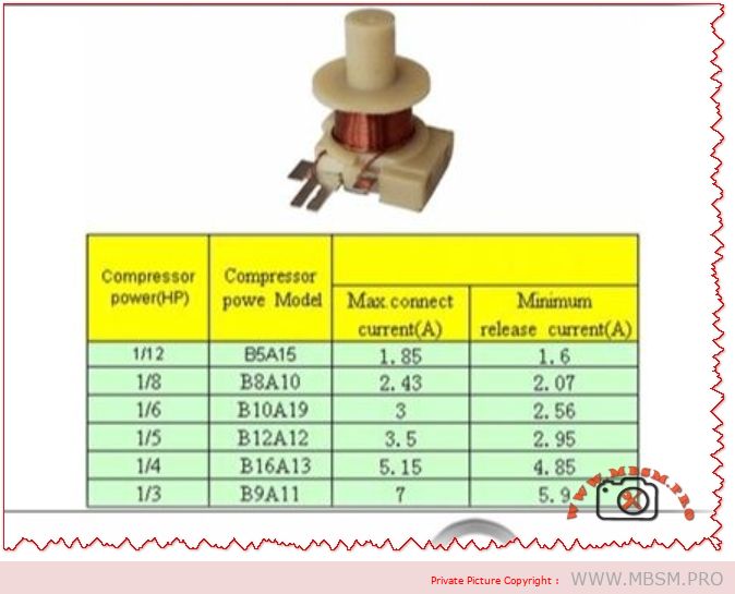
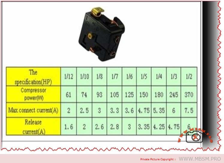
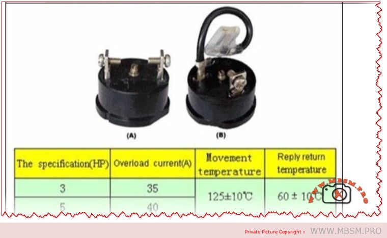
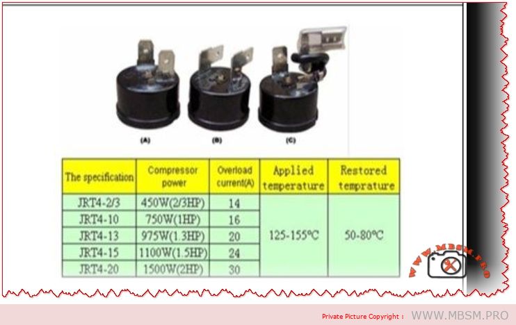
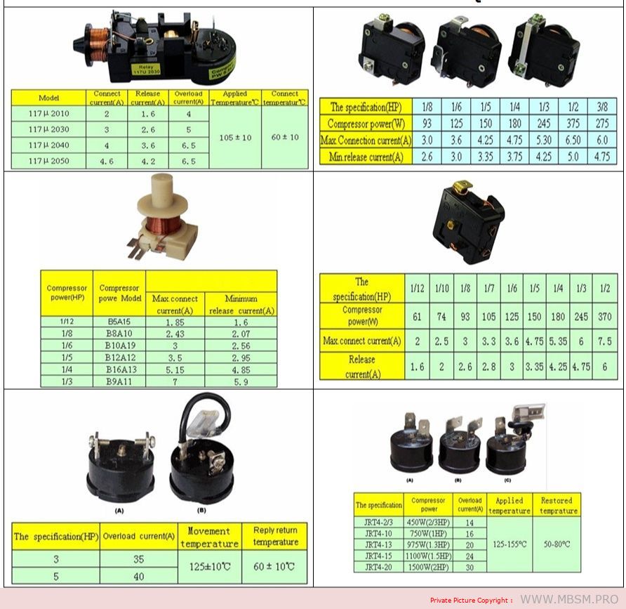
Compressor relay and OLP: the hidden guardians of your refrigerator compressor
Behind the plastic cover on the side of a refrigerator compressor, there is a small team of parts doing critical work: the start relay, the OLP (overload protector), and often a capacitor. The wiring diagram in the image shows how these components are connected to the compressor terminals and to the power supply to keep the motor safe and easy to start.
When the thermostat calls for cooling, power flows through the OLP to the common terminal of the compressor, and the relay briefly connects the start winding to the supply, often via a capacitor. Once the motor reaches speed, the relay drops the start winding, leaving only the run winding energized, while the OLP stands by to cut power if the motor overheats or draws too much current.
Key components in the wiring diagram
Compressor windings: Three pins marked C (common), R (run), and S (start), identified by resistance measurements with a multimeter.
Relay (PTC or current/voltage relay): Connects the start winding during startup, then automatically disconnects it when current or voltage conditions change.
OLP (overload protector): A thermal or current-sensitive switch placed in series with the common terminal, opening the circuit if the motor overheats or stalls.
Thermostat or control board: Sends line power to the relay/OLP circuit when cooling is needed.
Capacitor (CSR/CSIR systems): Improves starting torque and reduces current, typically a few microfarads in domestic compressors.
Typical wiring logic in refrigerator diagrams
The wiring diagram in the image is representative of many domestic fridges, where all components are tied together in a compact circuit.
Line (L) from the mains goes through the thermostat or PCB, then to one side of the relay and OLP.
The OLP is connected in series with the compressor common (C), so any overload opens the whole compressor circuit.
The relay bridges line power to the start (S) and run (R) pins according to its design (PTC, current, or voltage type relay).
Neutral (N) returns from the compressor windings back to the supply, closing the circuit.
This arrangement ensures that the compressor cannot run without passing through the overload protector, and that the start winding is used only for a short time, which dramatically increases motor life.
Table: Typical compressor relay–OLP connections
Function
Connection in circuit (typical fridge)
Notes for technicians
OLP input
Line from thermostat or control board
Always in series with compressor common.
OLP output
Compressor C terminal
Opens on overload/overheat.
Relay common terminal
Line or OLP output (depending on design)
Feeds S and R during start.
Relay output to start (S)
Compressor start pin via PTC or coil contact
Energized only at startup.
Relay output to run (R)
Compressor run pin, sometimes via capacitor
Stays energized in running mode.
Capacitor connection
Between S and R (CSR) or between line and auxiliary winding
Improves torque and reduces current.
Testing relay and OLP safely
Technicians often use a multimeter and a test cord to diagnose non-starting compressors in the field.
Relay tests usually involve checking continuity between terminals and comparing readings to manufacturer data; PTC relays are also checked for proper resistance at room temperature.
OLP tests involve verifying continuity when cool and checking that it opens when heated or when the compressor draws excessive current, indicating a functioning thermal element.
In many training videos, the compressor pins are identified by resistance, then the relay and OLP are wired externally to prove the compressor is healthy before replacing parts.
Why this diagram matters for Mbsmgroup, Mbsm.pro, and mbsmpro.com
For platforms like Mbsmgroup and Mbsm.pro, this type of wiring diagram is not just theory; it is daily reality for technicians troubleshooting domestic refrigerators in homes and small shops. Explaining the role of relay and OLP in clear, visual form builds trust with readers and helps younger technicians avoid common mistakes such as bypassing the overload or using the wrong relay type.
Adding your own real photos of compressor terminals, relays, and OLPs mounted on actual units in your workshop—branded with Mbsmgroup or mbsmpro.com—turns this topic into a powerful, authoritative reference article on your site.
Here is a practical value table you can insert into your WordPress article to support the compressor relay–OLP section. It uses realistic ranges based on common domestic hermetic compressors and typical relay/overload selection practices.
Table: Typical relay–OLP values for domestic refrigerator compressors
Approx. HP
Supply (V/Hz)
Typical FLA (A)
Typical LRA (A)
Recommended relay type
OLP trip current range (A)
Typical application
1/12 HP
220–240 V / 50
0.6–0.9
6–10
Small PTC relay module
1.2–1.6
Mini bar, very small refrigerator
1/10 HP
220–240 V / 50
0.8–1.1
8–14
PTC or solid-state relay
1.6–2.0
Single-door compact fridge
1/8 HP
220–240 V / 50
1.0–1.4
10–18
PTC / current relay
2.0–2.5
Small domestic fridge–freezer
1/6 HP
220–240 V / 50
1.3–1.8
14–24
PTC or CSR relay with capacitor
2.5–3.2
Standard top-freezer refrigerator
1/5 HP
220–240 V / 50
1.5–2.2
18–30
CSR relay (start capacitor + PTC/current)
3.0–3.8
Larger domestic fridge, small showcase
1/4 HP
220–240 V / 50
1.8–2.6
22–35
CSR relay with start capacitor
3.5–4.5
Large refrigerator / light commercial
1/3 HP
220–240 V / 50
2.3–3.5
30–50
High-torque CSR relay module
4.5–6.0
Commercial display, glass-door cooler
FLA (Full Load Amps) and LRA (Locked Rotor Amps) here are typical ranges; always check the exact values on the compressor nameplate and in its catalog before choosing a relay or OLP.
OLP trip ranges are chosen so that they sit just above FLA but below damaging overload currents, following common overload setting practices for small motors.
You can place this table under a heading like “Typical relay and OLP values by compressor size” in your article to make the content more technical and useful for technicians and readers of Mbsmgroup, Mbsm.pro, and mbsmpro.com.