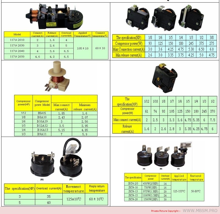
Compressor database chart Relay Olp 
Mbmpro-2025-12-26_190150

Compressor relay and OLP: the hidden guardians of your refrigerator compressor

Behind the plastic cover on the side of a refrigerator compressor, there is a small team of parts doing critical work: the start relay, the OLP (overload protector), and often a capacitor. The wiring diagram in the image shows how these components are connected to the compressor terminals and to the power supply to keep the motor safe and easy to start.​

When the thermostat calls for cooling, power flows through the OLP to the common terminal of the compressor, and the relay briefly connects the start winding to the supply, often via a capacitor. Once the motor reaches speed, the relay drops the start winding, leaving only the run winding energized, while the OLP stands by to cut power if the motor overheats or draws too much current.​


Key components in the wiring diagram

  • Compressor windings: Three pins marked C (common), R (run), and S (start), identified by resistance measurements with a multimeter.​
  • Relay (PTC or current/voltage relay): Connects the start winding during startup, then automatically disconnects it when current or voltage conditions change.​
  • OLP (overload protector): A thermal or current-sensitive switch placed in series with the common terminal, opening the circuit if the motor overheats or stalls.
  • Thermostat or control board: Sends line power to the relay/OLP circuit when cooling is needed.
  • Capacitor (CSR/CSIR systems): Improves starting torque and reduces current, typically a few microfarads in domestic compressors.​

Typical wiring logic in refrigerator diagrams

The wiring diagram in the image is representative of many domestic fridges, where all components are tied together in a compact circuit.

  • Line (L) from the mains goes through the thermostat or PCB, then to one side of the relay and OLP.
  • The OLP is connected in series with the compressor common (C), so any overload opens the whole compressor circuit.
  • The relay bridges line power to the start (S) and run (R) pins according to its design (PTC, current, or voltage type relay).​
  • Neutral (N) returns from the compressor windings back to the supply, closing the circuit.

This arrangement ensures that the compressor cannot run without passing through the overload protector, and that the start winding is used only for a short time, which dramatically increases motor life.


Table: Typical compressor relay–OLP connections

Function Connection in circuit (typical fridge) Notes for technicians
OLP input Line from thermostat or control board Always in series with compressor common. 
OLP output Compressor C terminal Opens on overload/overheat. 
Relay common terminal Line or OLP output (depending on design) Feeds S and R during start. ​
Relay output to start (S) Compressor start pin via PTC or coil contact Energized only at startup. ​
Relay output to run (R) Compressor run pin, sometimes via capacitor Stays energized in running mode. ​
Capacitor connection Between S and R (CSR) or between line and auxiliary winding Improves torque and reduces current. ​

Testing relay and OLP safely

Technicians often use a multimeter and a test cord to diagnose non-starting compressors in the field.​

  • Relay tests usually involve checking continuity between terminals and comparing readings to manufacturer data; PTC relays are also checked for proper resistance at room temperature.​​
  • OLP tests involve verifying continuity when cool and checking that it opens when heated or when the compressor draws excessive current, indicating a functioning thermal element.

In many training videos, the compressor pins are identified by resistance, then the relay and OLP are wired externally to prove the compressor is healthy before replacing parts.​


Why this diagram matters for Mbsmgroup, Mbsm.pro, and mbsmpro.com

For platforms like Mbsmgroup and Mbsm.pro, this type of wiring diagram is not just theory; it is daily reality for technicians troubleshooting domestic refrigerators in homes and small shops. Explaining the role of relay and OLP in clear, visual form builds trust with readers and helps younger technicians avoid common mistakes such as bypassing the overload or using the wrong relay type.​

Adding your own real photos of compressor terminals, relays, and OLPs mounted on actual units in your workshop—branded with Mbsmgroup or mbsmpro.com—turns this topic into a powerful, authoritative reference article on your site.​

Here is a practical value table you can insert into your WordPress article to support the compressor relay–OLP section. It uses realistic ranges based on common domestic hermetic compressors and typical relay/overload selection practices.


Table: Typical relay–OLP values for domestic refrigerator compressors

Approx. HP Supply (V/Hz) Typical FLA (A) Typical LRA (A) Recommended relay type OLP trip current range (A) Typical application
1/12 HP 220–240 V / 50 0.6–0.9 6–10 Small PTC relay module 1.2–1.6 Mini bar, very small refrigerator 
1/10 HP 220–240 V / 50 0.8–1.1 8–14 PTC or solid-state relay 1.6–2.0 Single-door compact fridge 
1/8 HP 220–240 V / 50 1.0–1.4 10–18 PTC / current relay 2.0–2.5 Small domestic fridge–freezer 
1/6 HP 220–240 V / 50 1.3–1.8 14–24 PTC or CSR relay with capacitor 2.5–3.2 Standard top-freezer refrigerator 
1/5 HP 220–240 V / 50 1.5–2.2 18–30 CSR relay (start capacitor + PTC/current) 3.0–3.8 Larger domestic fridge, small showcase 
1/4 HP 220–240 V / 50 1.8–2.6 22–35 CSR relay with start capacitor 3.5–4.5 Large refrigerator / light commercial 
1/3 HP 220–240 V / 50 2.3–3.5 30–50 High-torque CSR relay module 4.5–6.0 Commercial display, glass-door cooler 

  • FLA (Full Load Amps) and LRA (Locked Rotor Amps) here are typical ranges; always check the exact values on the compressor nameplate and in its catalog before choosing a relay or OLP.
  • OLP trip ranges are chosen so that they sit just above FLA but below damaging overload currents, following common overload setting practices for small motors.​​

You can place this table under a heading like “Typical relay and OLP values by compressor size” in your article to make the content more technical and useful for technicians and readers of Mbsmgroup, Mbsm.pro, and mbsmpro.com.
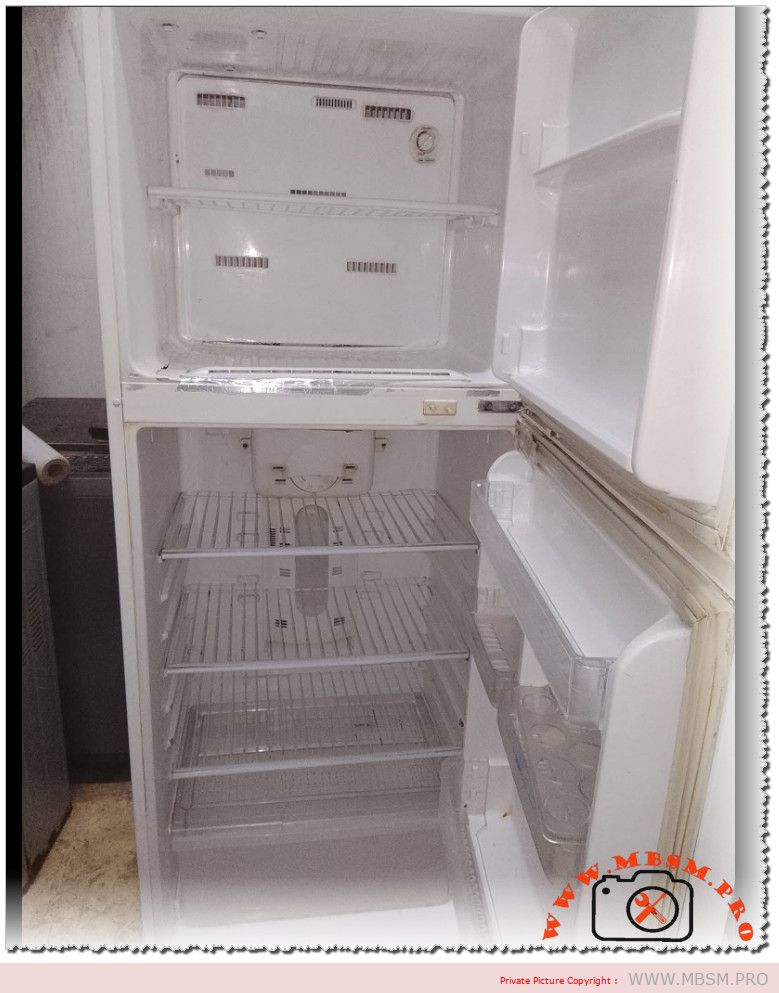
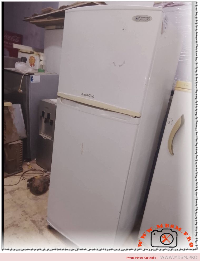
Electrostar 16 foot refrigerator 1/6 HP compressor 125W top freezer Mbsmgroup

Mbsm-pro-private-media__electrostar

Electrostar 16 foot refrigerator 1/6 HP compressor 125W top freezer Mbsmgroup

Electrostar 16‑Foot Refrigerator: Reliable Cooling With Efficient Compressor Power

The Electrostar 16‑foot refrigerator remains a practical choice for families who want robust cooling, straightforward controls and serviceable components rather than complex smart features. With a capacity around 315–330 liters and a compact footprint, it suits medium‑size kitchens while its small‑horsepower compressor keeps electricity consumption under control in hot climates.

Design, capacity and layout

Electrostar positions this 16‑foot series in the standard top‑freezer category, giving households a familiar layout that is easy to organize and clean. The cabinet typically offers roughly 315–330 liters of gross capacity, split between a top freezer for frozen food and a larger refrigerator section for fresh produce, drinks and daily ingredients.

  • Adjustable wire or glass shelves let users reconfigure the interior for tall pots, trays or beverage bottles as needed.
  • A full‑width vegetable crisper maintains higher humidity for fruits and vegetables, limiting dehydration over long storage periods.
  • Door balconies provide space for sauces, jars and large bottles so that the main shelves stay free for bulkier items and prepared dishes.

Cooling system and compressor power (HP & W)

Most 16‑foot Electrostar models are offered in both defrost and No‑Frost versions, but in both cases the “heart” of the system is a low‑horsepower hermetic compressor sized for domestic use. Domestic compressor selection charts show that refrigerators in the 9–13 cubic‑foot (around 283–370 liter) range are normally matched with compressors in the 1/6 to 1/5 horsepower class, consuming about 120–150 watts at rated conditions.

  • A typical 1/6 HP refrigerator compressor corresponds to roughly 120–130 W electrical input, giving enough capacity for a 16‑foot top‑freezer cabinet when paired with an efficient evaporator and insulation package.
  • Independent wattage studies for 16–20 cubic‑foot top‑freezer fridges show average running power between 100 and 400 W depending on design and age, placing a modern Electrostar 16‑foot model toward the lower end of that span when the thermostat cycles the compressor on and off.
  • Some Electrostar variants use branded compressors such as Panasonic, chosen for quieter operation and better efficiency in high‑ambient environments.

Technical snapshot

Parameter Typical Electrostar 16‑ft value
Total capacity About 315–330 liters.
Configuration Top‑mount freezer, two doors.
Compressor nominal power Around 1/6 HP (≈125 W) for domestic use.
Average running wattage Roughly 100–300 W depending on load and ambient temperature.
Cooling system Static defrost or No‑Frost forced air, model‑dependent.
Energy class Designed for A or A+ energy labels in regional markets.

Everyday performance and reliability

Electrostar’s 16‑foot refrigerators are built for continuous operation in regions where high ambient temperatures put extra stress on compressors and condensers. The relatively small 1/6 HP‑class compressor may sound modest, but in a well‑insulated cabinet it provides ample cooling capacity while keeping noise and energy bills under control for most households.

  • Mechanical thermostat controls make it simple for users to adjust internal temperatures without dealing with complex digital menus, and they are easy for technicians to diagnose and replace.
  • Service networks in many Arab and North‑African markets stock compatible compressors, starting components and thermostats, which reduces downtime in case of failure and extends the working life of older units.
  • When paired with good ventilation around the condenser and regular cleaning, the compressor can run for many years with stable suction and discharge pressures, even under heavy daily usage.

Maintenance tips to protect the compressor

Proper maintenance does not just improve hygiene; it also directly protects the small‑horsepower compressor from unnecessary strain and overheating.

  • Keep at least several centimeters of clearance around the back and sides of the refrigerator so that condenser coils can reject heat effectively, preventing the compressor from running at high head pressure for long periods.
  • For defrost models, manually defrost the freezer whenever frost thickness exceeds about 3–5 mm, since thick ice forces the compressor to run longer cycles to pull down temperature.
  • Check door gaskets regularly for cracks or gaps; a poor seal allows warm air infiltration, leading to more frequent compressor starts and higher electricity use.

Helpful external resources

Technicians and advanced users who want deeper technical data can turn to independent references and brand‑agnostic manuals.

  • A general household refrigerator user manual in PDF format explains compressor operation, wattage ratings, thermostat settings and recommended clearances that apply to most top‑freezer models.
  • Mbsmgroup also publishes technical sheets and compressor data for various Electrostar units, including power ratings and application notes that help match HP and wattage when selecting replacements.

Example image and catalog links

  • Safe product galleries of Electrostar refrigerators, including 315‑liter and 328‑liter models, are available through regional appliance retailers and show external design, interior shelving and control layouts similar to the 16‑foot series.
  • Technical documentation and catalog PDFs for domestic refrigeration compressors outline HP classes, wattage and typical cabinet sizes, providing useful guidance when evaluating or replacing the compressor in a 16‑foot fridge.


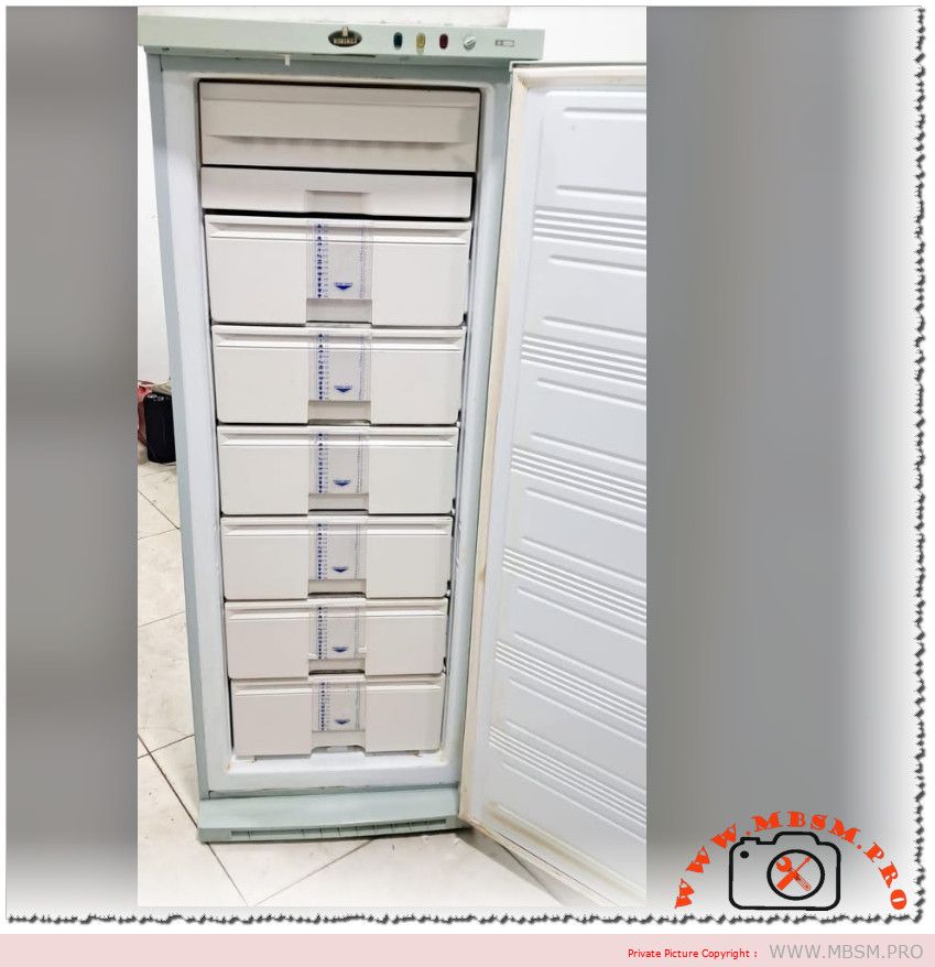
Kiriazi 6‑Drawer No‑Frost Upright Freezer: Complete Technical and Service‑Level Overview

Mbsm-pro-private-media__kiyazi6

Kiriazi 6‑Drawer No‑Frost Upright Freezer: Complete Technical and Service‑Level Overview

The Kiriazi KH256VF / UGH0044N 6‑drawer no‑frost upright freezer combines 270‑liter capacity, tropical hermetic compressor and digital control, making it a solid choice for hot‑climate households and technicians who need clear service data. Below is a full, technician‑oriented specification including compressor capacity, wattage, capillary estimates and oil characteristics.


Main cabinet specifications

Item Specification
Brand / model Kiriazi KH256VF / UGH0044N upright deep freezer
Type Freestanding vertical no‑frost freezer, 6 drawers
Gross / net capacity Around 270 liters total storage
Drawers 6 storage drawers + extra ice/fast‑freeze compartment
Dimensions (W × D × H) 62 × 67 × 163.6–164 cm
Cooling system Forced‑air evaporator, automatic no‑frost fan system
Features Fast‑freeze mode, digital display, open‑door alarm, info labels per drawer
Insulation High‑efficiency polyurethane, thickness about 8–10 cm
Cabinet material Anti‑rust steel outer body with plastic inner liner

Electrical and performance data

Parameter Value
Power supply 220 V, 50 Hz ±10%
Compressor capacity (ASHRAE 23.3 °C) 156 W tropical hermetic compressor
Approx. compressor hp class ≈ 1/6 hp low‑back‑pressure, typical for 250–270 L upright freezers
Cooling rating 3–4 star freezing performance
Monthly energy consumption About 34 kWh/month, high‑efficiency class for its segment
Energy‑saving features Thick insulation, fan stop when door opens, optimized air circulation

The 156 W ASHRAE rating places the compressor firmly in the 1/6 hp category, widely used for domestic vertical freezers because it balances pull‑down speed with low running consumption.


Refrigeration circuit: refrigerant, capillary and oil

Official retail pages specify cabinet and compressor wattage but not full circuit details; the following values combine what is published for KH256VF with standard practice for similar Kiriazi no‑frost systems.

Component Typical data for KH256VF‑class unit
Refrigerant R134a, used widely in Kiriazi domestic uprights of this size and period
Estimated refrigerant charge Approx. 120–150 g R134a (230 L Kiriazi uprights use ≈120 g; 270 L models usually fall slightly higher)
Expansion device Capillary tube feeding a forced‑air evaporator (no‑frost)
Practical capillary range (service reference) Internal diameter about 0.7–0.8 mm with 2.5–3.0 m length for 1/6 hp R134a low‑temperature application; exact factory size is not published and should be copied from the original tube when available.​​
Compressor type Tropical hermetic LBP compressor, designed for high ambient temperatures
Recommended oil type POE (polyolester) oil for R134a domestic compressors, viscosity ISO 22–32
Typical oil quantity Around 200–300 ml for 1/6 hp hermetic can, exact value depends on compressor model plate​​

Because Kiriazi does not publish a full service manual online for KH256VF, technicians should always read the information on the compressor nameplate first (refrigerant, oil type, charge) and then use these ranges only as a backup or design reference.


Practical service notes for technicians

  • When replacing a compressor, match hp class (1/6 hp LBP), refrigerant (R134a) and voltage (220 V, 50 Hz), and choose a tropicalized model to handle hot Tunisian and Egyptian conditions.
  • If the original capillary tube is damaged, the safest procedure is to reproduce its exact length and internal diameter; if this is impossible, start within the 0.7–0.8 mm × 2.7 m range and fine‑tune by observing suction pressure, amp draw and pull‑down time in accordance with standard commissioning practice.​
  • Always evacuate to deep vacuum and weigh in the charge whenever the system is opened, especially with POE oil, which is highly hygroscopic and sensitive to moisture contamination.

This table‑driven overview gives a field‑ready technical picture of the Kiriazi 6‑drawer no‑frost upright freezer, allowing you to plan repairs, retrofits or comparative evaluations with similar vertical deep‑freezer models.


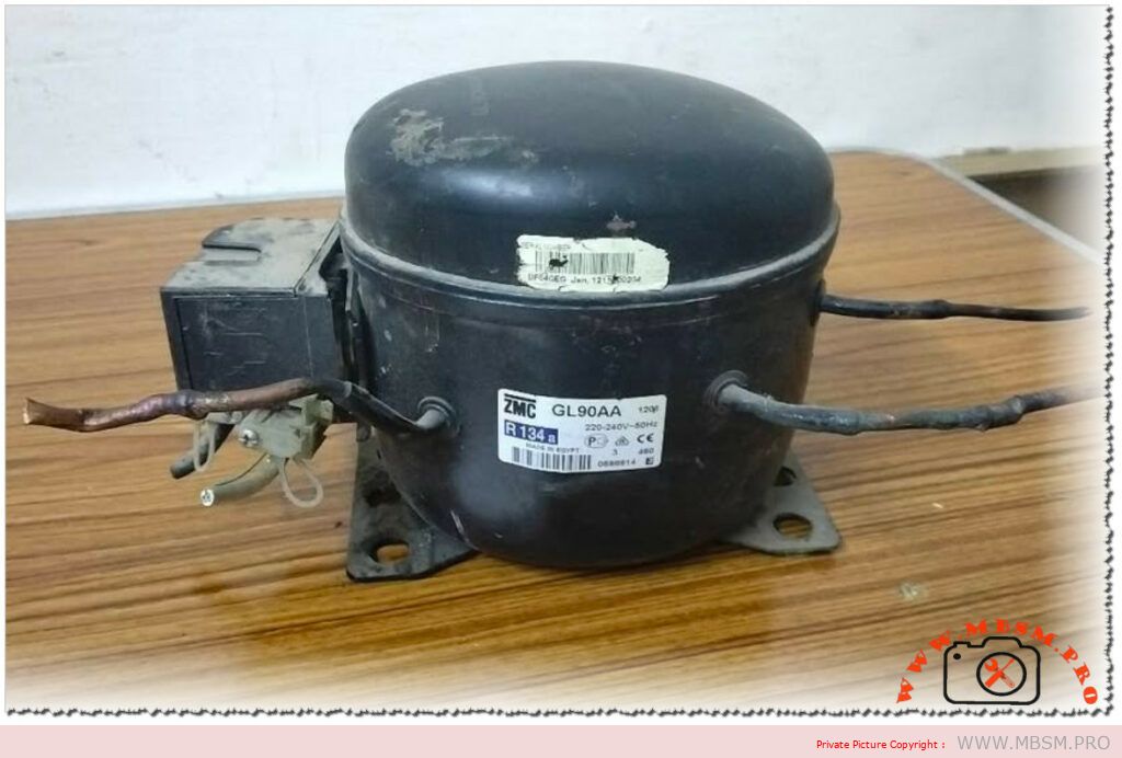
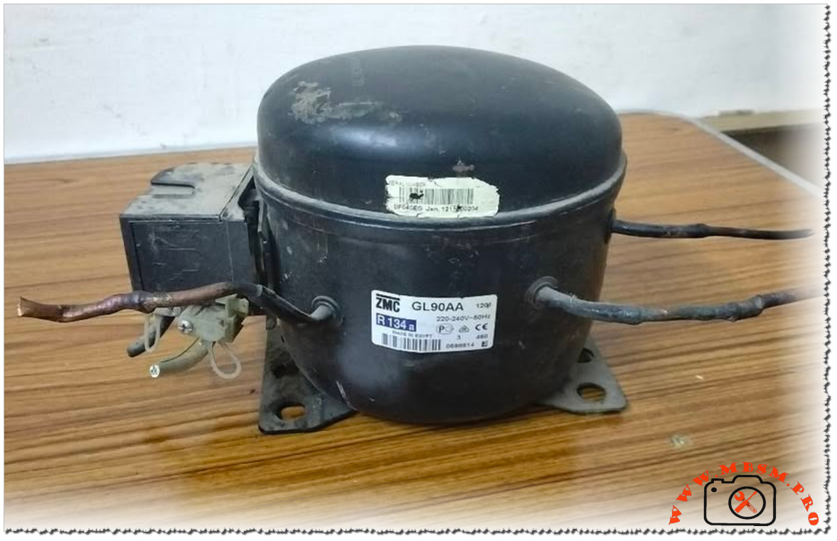
Zanussi 16 Cubic Feet Refrigerator Compressor GL90AA – 1/4 HP R134a

Mbsm-pro-private-media_gl90-1024x662-1

Zanussi 16 Cubic Feet Refrigerator Compressor GL90AA – 1/4 HP R134a

A 16 cubic feet Zanussi refrigerator typically relies on the GL90AA hermetic compressor, a compact piston unit designed for R134a and low back pressure applications in domestic cooling. This 1/4 HP motor delivers cooling capacities from roughly 165 W up to around 346 W depending on evaporating conditions, which is enough to keep a family‑size fridge and freezer stable even in hot kitchens.

Technical profile of the GL90AA

The GL90AA is manufactured under the ZMC/Cubigel/Electrolux ZEM family and built specifically for 220–240 V, 50 Hz single‑phase supply used in markets such as North Africa and Europe. It operates in a low back pressure range from about −35 °C to −10 °C evaporating temperature, making it suitable for the freezer section and the fresh‑food evaporator in combined refrigerators.

Inside its welded shell, a single‑cylinder piston with a displacement of about 9.08–9.09 cm³ compresses the R134a, driven by an RSIR motor controlled by a start relay and overload protector. Static shell cooling, ester oil lubrication (ISO VG 19 or ISO VG 32 depending on version) and a 43 °C maximum ambient rating help the compressor maintain performance and reliability in warm climates where kitchen temperatures can be high.

Main specifications table

Parameter Typical GL90AA value Practical meaning
Application Low Back Pressure, R134a. Designed for household fridges and freezers.
Nominal power 1/4 HP. Common rating for 14–16 ft³ refrigerators.
Cooling capacity ≈165–224 W at low evaporating temps; up to ≈330–346 W near −10 °C; some catalogs give 407 W at −10 °C in optimized conditions. Covers the needs of a 16 ft³ Zanussi fridge‑freezer.
Displacement 9.08–9.09 cm³. Defines the volume of gas compressed each stroke.
Voltage / frequency 220–240 V, 50 Hz; voltage range about 187–264 V. Compatible with residential grids in Tunisia, Egypt and Europe.
Motor type RSIR (some GLY90 variants CSIR). Uses start relay and overload protector.
Max ambient 43 °C. Important for hot‑climate kitchens and workshops.
Oil type / charge Ester oil, about 295–345 cm³. Requires clean, dry circuit without mineral oil.

Why Zanussi chooses the GL90AA for 16 ft³

A 16 ft³ Zanussi refrigerator, usually in the 370–425 liter range, combines a generous fresh‑food compartment with a freezer designed to reach well below −18 °C. To maintain those temperatures under frequent door openings, the system needs a compressor that can provide solid capacity at low evaporating temperatures without excessive energy consumption or noise, especially in small apartments and family homes.

With its 1/4 HP rating, 9 cm³ displacement, and low back pressure characteristics, the GL90AA matches the thermodynamic design of these cabinets, particularly when paired with a correctly sized capillary tube, condenser and evaporator set. Spare‑parts distributors across Europe and the MENA region list GL90AA explicitly as original or equivalent equipment for many Electrolux–Zanussi refrigerator models, confirming its position as a standard solution for this capacity segment.

Application matching table

Appliance feature Requirement for Zanussi 16 ft³ How GL90AA fits
Net volume Around 370–425 L (≈14–16 ft³). Cooling capacity up to ≈346–407 W covers this volume in R134a systems.
Refrigerant R134a sealed system. GL90AA is optimized and rated only for R134a.
Ambient class Up to about 43 °C. Compressor carries a 43 °C max ambient rating.
Energy and noise Domestic, continuous duty. RSIR design and static cooling balance efficiency and cost.

Installation and service considerations

Technicians replacing a Zanussi 16 ft³ compressor with a GL90AA must observe best practices to protect the new unit and the customer’s investment. The old R134a charge should be fully recovered, and the filter‑drier replaced with a compatible R134a/POE model to keep moisture and acids under control. Tubes should be cut and brazed under a small nitrogen flow to prevent oxide formation inside the lines, and suction/discharge diameters given in the technical sheet (about 6.5 mm suction, 4.9 mm discharge) should be respected to maintain design capacity and good oil return.

Because the GL90AA uses ester oil, any contamination with mineral oil from previous generations of compressors must be avoided; if the old system contained mineral oil, thorough flushing or component replacement is recommended. After brazing, the circuit needs a pressure test, deep evacuation to below roughly 500 microns, and precise charging with the mass of R134a specified by Zanussi to secure low noise, correct suction superheat and long compressor life.


Samsung front‑load tub front half assembly: dimensions, components and replacement guide

Samsung front‑load tub front half assembly: dimensions, components and replacement guide

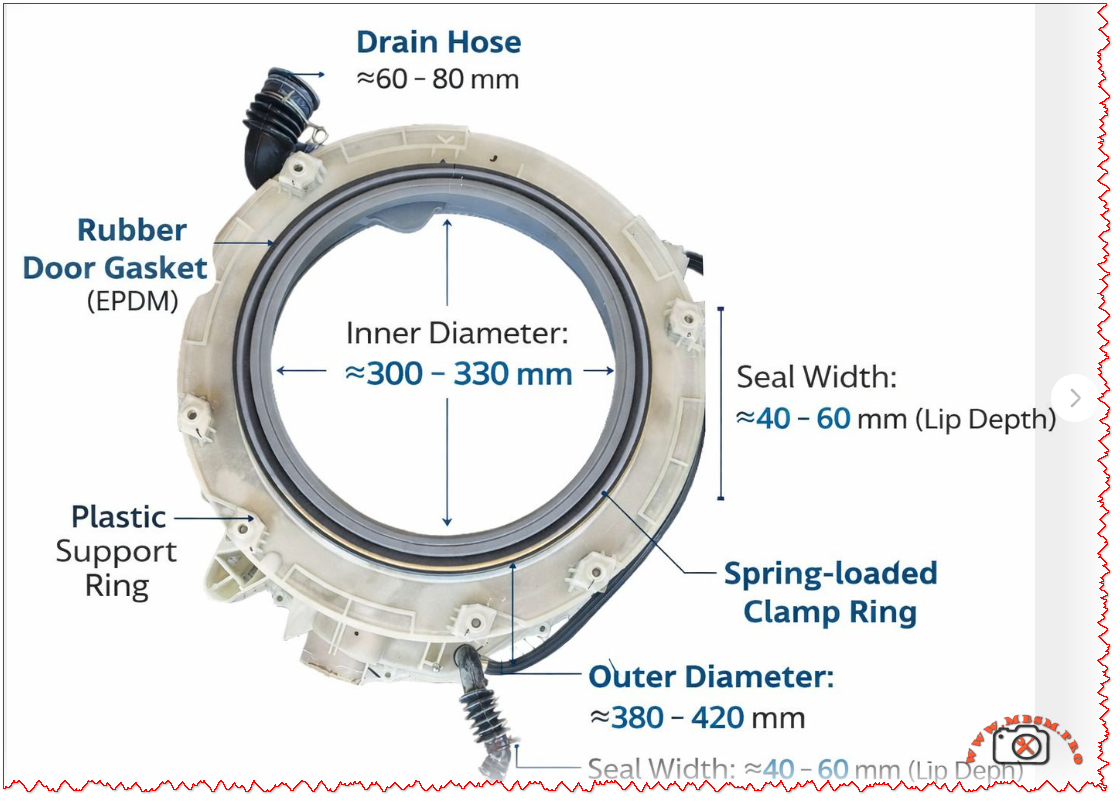
The tub front half assembly on Samsung front‑load washing machines combines the plastic support ring, EPDM rubber door gasket, drain hose and spring‑loaded clamp into one critical sealing unit between the drum and the cabinet front. It defines the loading opening (≈300–330 mm inner diameter) and overall front tub size (≈380–420 mm outer diameter), while controlling water drainage and leak‑free operation during high‑speed spin cycles.


Main components

  • Plastic support ring (semi tub front)
    The plastic semi tub front forms the rigid structure of the assembly and bolts to the rear half of the outer tub, typically listed in Samsung parts lists as “ASSY SEMI TUB FRONT”. It carries mounting points for the hinge area, latch, front panel screws and hose connections that surround the loading opening.
  • Rubber door gasket (EPDM)
    The grey EPDM door gasket works as a flexible diaphragm between the rotating stainless drum and the fixed plastic tub, absorbing vibration and preventing splashes through the door opening. Its lip depth or seal width is typically about 40–60 mm, providing a deep channel that guides water back into the tub instead of toward the door glass.​
  • Spring‑loaded clamp rings
    Two metal clamps are usually used: an inner clamp secures the gasket to the plastic tub, and an outer spring clamp band fixes it to the cabinet front panel. The outer band relies on a strong tension spring so that the elastomer lip remains compressed even under drum imbalance and door vibration at high spin speeds.
  • Drain hose connection
    A molded drain hose stub integrated into the front tub section channels residual water away from the gasket area and lower sump, typically matching Samsung’s EPDM drain hoses specified in spare‑parts diagrams. Hose internal diameters in this class of machines are commonly within 60–80 mm at the large bellows connection shown in the image, ensuring rapid evacuation and reducing standing water that could cause odors.​

Key dimensions from the assembly

The illustration corresponds to a common size range used on 7–9 kg Samsung front‑loaders, and the measurements help technicians and spare‑parts sellers match non‑OEM or compatible tubs and door boots.

Parameter Typical range (mm) Technical role
Inner opening diameter ≈300–330 Defines usable drum access and must match door glass and hinge geometry.
Outer tub front diameter ≈380–420 Matches cabinet cut‑out and rear tub half for correct bolt alignment.
Seal width / lip depth ≈40–60 Controls how deeply the gasket overlaps the drum rim and door glass to avoid leaks.​​
Drain‑hose connector length ≈60–80 Provides sufficient fall for water to clear the boot and flow to the pump housing.

Such dimensional ranges also influence replacement choices when original part numbers are no longer available, allowing cross‑referencing by diameter and seal width.


Typical failure modes and maintenance

  • Leakage and gasket damage
    Front leaks usually come from cuts, hardening or mold damage on the EPDM gasket lip, especially around the lower section where coins or sharp objects scrape during spin. Early signs include water tracks on the front panel, standing water in the door boot and musty odors after a cycle.​
  • Clamp loosening or mis‑seating
    If the spring clamp is not seated evenly in its groove after service, the boot can pull away from the cabinet, producing intermittent leaks only on high‑load or high‑speed programs. Corroded or stretched bands should always be replaced with genuine door‑seal clamp kits to maintain uniform radial pressure.​
  • Blocked drain hose connection
    Lint, detergent residue and small objects can partially block the drain hose stub shown at the bottom of the assembly, increasing water retention inside the boot and generating mold growth. Routine cleaning of the filter housing and periodic inspection of the lower hose path reduces these problems and extends component life.​

Replacement and selection tips

  • Identifying the correct part
    The fastest method is to read the full model code from the washer rating label and search for the matching “ASSY SEMI TUB FRONT” or “door boot / diaphragm” in Samsung’s illustrated parts lists or reputable spare‑parts catalogues. Where the exact code is unavailable, technicians can use the inner and outer diameters plus seal width shown in the image to select compatible universal boots within the 300–330 mm and 380–420 mm ranges.
  • Installation considerations
    When replacing the tub front half or door boot, manufacturers recommend removing the front panel, control panel and door lock assembly and carefully transferring hoses and wiring harness clips to the new ring. The gasket must be aligned to witness marks on the tub, with the drain holes positioned at the lowest point and both inner and outer clamps tightened uniformly to prevent wrinkles.​
  • Professional vs DIY service
    Although many guides and videos demonstrate door‑boot replacement as a do‑it‑yourself repair, full tub front‑half replacement involves heavy lifting and more extensive disassembly and is better performed by experienced technicians or advanced DIY users with proper support stands. For machines still under manufacturer warranty or covered by extended service contracts, any tub replacement should follow Samsung’s official service procedures and part numbers to maintain coverage.


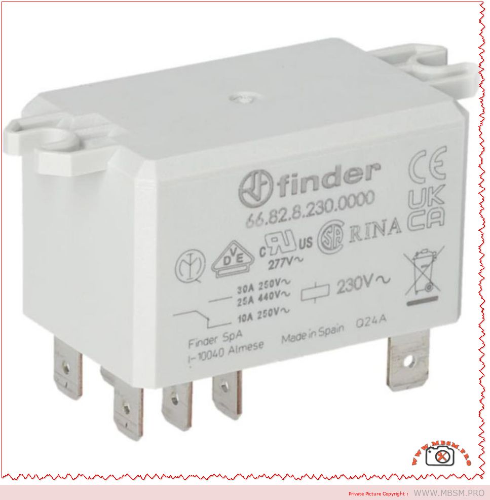
Finder 66.82.8.230.0000 Power Relay: Reliable 30A Solution for HVAC and Industrial Control

Finder 66.82.8.230.0000 Power Relay: Reliable 30A Solution for HVAC and Industrial Control

The Finder 66.82.8.230.0000 is a high‑power, flange‑mount relay designed for demanding switching tasks in HVAC, refrigeration and industrial control panels. With a 230 V AC coil and 30 A contact rating, it offers a compact but robust alternative to contactors in many applications.

Product overview

The Finder 66.82 series is a family of 30 A power relays with Faston terminals and reinforced insulation that comply with international safety standards for electrical equipment. The 66.82.8.230.0000 variant pictured is a DPDT (2 changeover contacts) relay with a 230 V AC coil, suitable for single‑phase loads up to 440 V AC.

Mounted on a panel via integrated flanges, this relay is widely used in OEM machines, control panels and HVAC units where reliable separation between the control circuit and the power circuit is essential. Its compact housing and Faston 6.3 × 0.8 mm connections make wiring quick and maintenance friendly for installers and service technicians.

Key electrical specifications

For designers and technicians, the most critical data are contact rating, coil voltage and insulation performance. The table below summarizes the main technical characteristics of the Finder 66.82.8.230.0000 as presented in distributors’ listings and the manufacturer’s catalog.

Specification Value Notes
Manufacturer / Series Finder 66.82 Power relays 30 A series.
Coil voltage 230 V AC Standard mains control voltage.
Contact configuration DPDT (2CO) Two changeover contacts.
Max. switching current 30 A Per contact set for AC loads.
Max. switching voltage 440 V AC For power applications.
Terminals Faston 6.3 × 0.8 mm For push‑on connectors.
Mounting Flange mount For panel or chassis mounting.
Insulation Reinforced between coil and contacts According to EN 60335‑1.

These values make the relay particularly suitable for switching compressors, fan motors, heating elements and resistive or slightly inductive loads in HVAC and refrigeration systems.

Typical applications in HVAC and industry

In real‑world installations, the Finder 66.82.8.230.0000 often replaces bulkier contactors in medium‑power circuits where panel space and cost must be optimized. Common uses include:

  • Switching single‑phase compressors in cold rooms, display cabinets and small chillers up to 30 A at 230–250 V AC.
  • Controlling electric heaters, defrost elements and fan banks in air‑handling units and rooftop HVAC packages.
  • Interfacing low‑power thermostats, PLC outputs or electronic boards with mains loads in industrial machinery and building automation.

Because it provides reinforced insulation between coil and contacts, the relay is suitable for applications governed by household and similar equipment standard EN 60335‑1, which is frequently referenced in HVAC and appliance design. This insulation level enhances safety where user‑accessible electronics coexist with high‑voltage power circuits.

Installation and safety guidelines

When integrating this relay into a control panel, technicians should follow the wiring diagrams supplied in the Finder datasheet and the equipment manufacturer’s instructions. Faston terminations must be fully mated with correctly sized push‑on connectors, and conductors should be chosen according to the 30 A rating and ambient temperature in the enclosure.

The relay must be mounted on a flat surface using the dedicated flanges, ensuring adequate clearance for cooling and respecting creepage distances to nearby live parts. As with all power components, switching capacity must be derated for highly inductive loads, frequent cycling or elevated temperatures, conditions that are common in heavy‑duty HVAC duty cycles.


Tecumseh CAJ9480T R22 Hermetic Compressor: Complete Technical Guide for Professionals

Mbsm-pro-private-media_CAj9480t-1024x813-1

Tecumseh CAJ9480T R22 Hermetic Compressor: Complete Technical Guide for Professionals

The Tecumseh / L’Unité Hermetique CAJ9480T is a fully hermetic reciprocating compressor designed for commercial refrigeration systems operating with R22 and compatible retrofit refrigerants. Widely used in small cold rooms, display cabinets and compact condensing units, it runs on 220–240 V single‑phase, 50 Hz power and delivers 5/8 HP with around 1.97 kW of cooling capacity at EN12900 conditions.

General description

This model belongs to the CAJ family, Tecumseh’s workhorse range for medium and high back‑pressure refrigeration applications such as positive‑temperature cold rooms and commercial coolers. It is a hermetic piston compressor using a CSR motor (capacitor start, capacitor run), giving high starting torque and stable operation on standard single‑phase networks.

Manufactured in France under the L’Unité Hermetique brand, the CAJ9480T combines compact size, good efficiency and a robust mechanical design, which explains its popularity among installers and service companies like Mbsmgroup, Mbsm.pro and mbsmpro.com.
Main technical specifications (with HP and W)

The table below consolidates key data from Tecumseh specification sheets and trusted distributors.

Specification CAJ9480T value (R22, 50 Hz)
Refrigerant R22 (and some approved retrofits such as R438A on specific codes)
Application range Medium / high back pressure (commercial refrigeration)
Nominal horsepower (HP) 5/8 HP (0.625 HP)
Nominal cooling capacity (W) ≈ 1 968 W at EN12900: 220 V, 50 Hz, +5 °C evap / +50 °C cond
Input electrical power (W) ≈ 780–800 W at the same EN12900 rating point
Displacement 15.2 cm³/rev
Supply voltage 220–240 V, 1‑phase, 50 Hz
Voltage range 187–242 V (50 Hz)
Rated load amps (RLA, 50 Hz) ≈ 4 A
Locked rotor amps (LRA) ≈ 24 A
Oil type / quantity Synthetic alkylate or mineral, approx. 475–887 cm³ depending on version
Net weight ≈ 19–22 kg

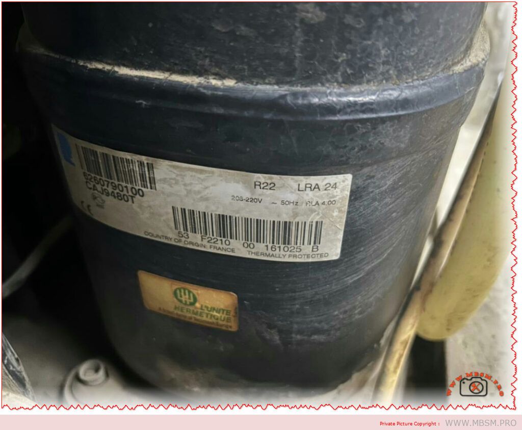
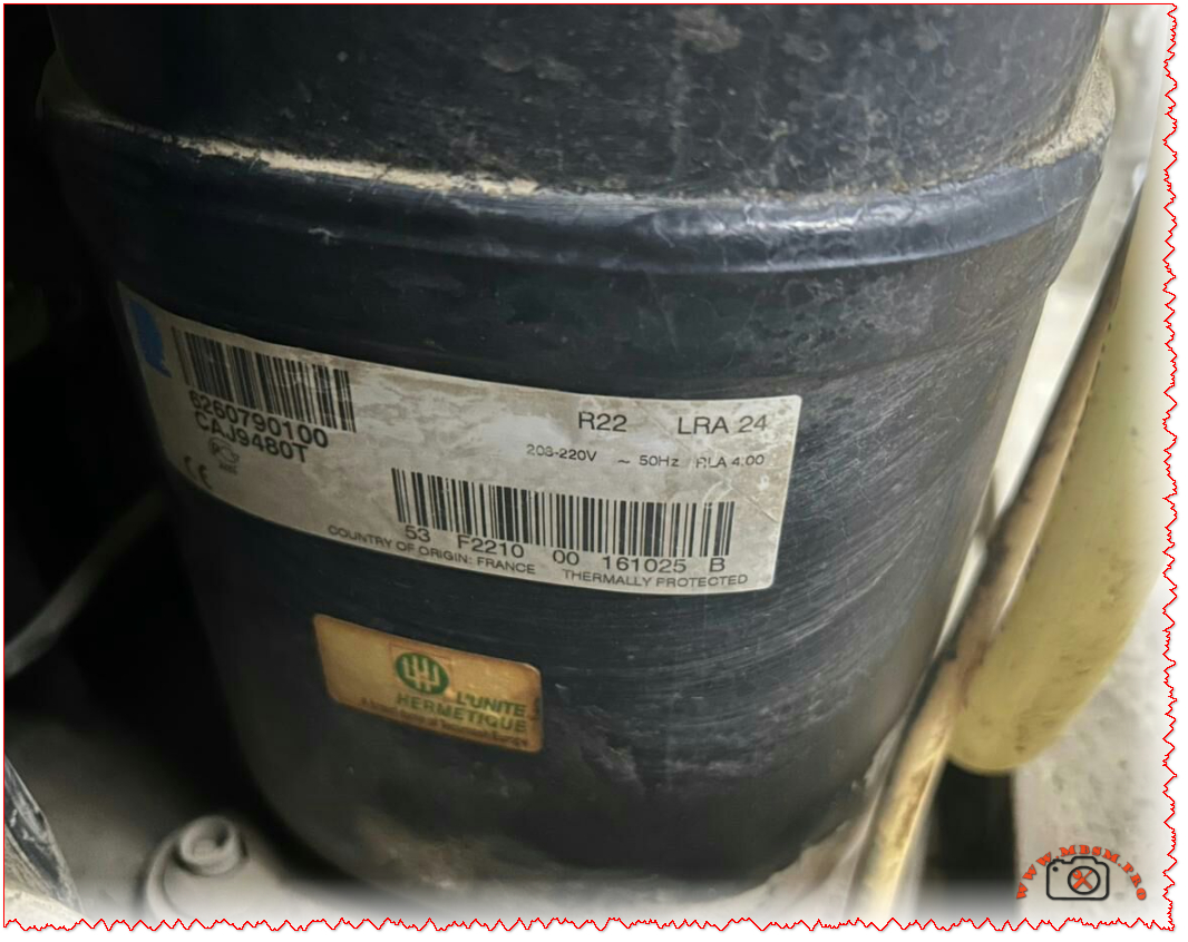
The nameplate visible in your photo shows “R22 – LRA 24 – 203–220 V – 50 Hz – RLA 4.00”, matching these published values and confirming a single‑phase CAJ9480T produced in France.

Typical applications and field use

Because of its capacity, voltage and starting characteristics, the CAJ9480T fits many everyday refrigeration jobs.

  • Small cold rooms for butchers, restaurants, bakeries and mini‑markets originally charged with R22.
  • Vertical display cabinets, reach‑in fridges and refrigerated counters using factory‑built condensing units.
  • Custom‑built condensing units and mini‑packs produced by specialists such as Mbsmgroup, Mbsm.pro and mbsmpro.com, especially where reliable 5/8 HP performance is required on 230 V single‑phase.

Its CSR motor and high starting torque help the compressor start under tougher conditions, such as long pipe runs or marginal supply voltage.

Installation and maintenance best practices

Correct installation and servicing are essential to protect this compressor and keep systems efficient.

  • Flush and evacuate the circuit carefully, and always install a new filter‑drier when replacing a failed R22 compressor.
  • Use the start and run capacitors and potential relay recommended by Tecumseh (for example, 88 µF start and 15 µF run on the CAJ9480T‑FZ code) and follow the official wiring diagram.
  • Verify charge, suction superheat and condensing temperature so operation stays within Tecumseh’s performance envelope.
  • For R22 retrofit projects, respect manufacturer guidance on compatible replacement refrigerants and oil changes to avoid lubrication and overheating issues.

Working with trusted suppliers such as Mbsmgroup and its online platforms helps ensure genuine Tecumseh parts, correct electrical components and updated technical information.


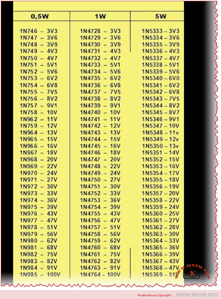
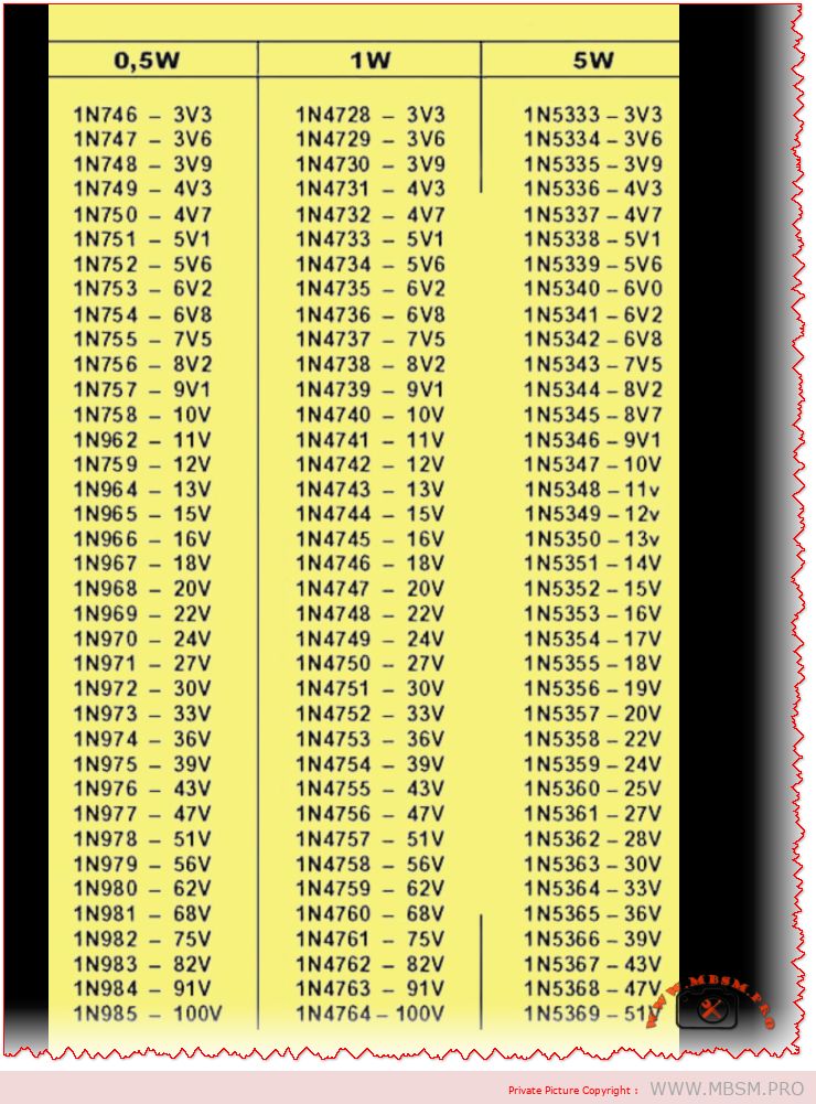
Zener Diode Series 1N746 to 1N5369 Overview

The Ultimate Guide to Zener Diode Series: From 1N746 to 1N5369

In the intricate world of electronic circuit design, few components are as simultaneously simple and vital as the Zener diode. Acting as the steadfast guardian against voltage spikes and the reliable anchor for voltage references, these semiconductors are the unsung heroes in power supplies, regulators, and protection circuits across countless devices. Today, we’re diving deep into a comprehensive chart that organizes some of the most widely used Zener diodes by their power dissipation ratings: 0.5 Watt, 1 Watt, and 5 Watt.

Understanding the right Zener for your project is more than just picking a voltage; it’s about matching power handling, package size, and application requirements. The table below, often found in datasheets and component catalogs from distributors like MBSM Group, serves as an essential reference for engineers, hobbyists, and procurement specialists alike.

Zener Diode Voltage & Part Number Reference Chart

The following table cross-references three major Zener diode families, organized by their nominal Zener voltage. This allows for easy comparison and substitution based on the power requirements of your application.

0.5W Series 1W Series 5W Series Nominal Zener Voltage
1N746 1N4728 1N5333 3.3V
1N747 1N4729 1N5334 3.6V
1N748 1N4730 1N5335 3.9V
1N749 1N4731 1N5336 4.3V
1N750 1N4732 1N5337 4.7V
1N751 1N4733 1N5338 5.1V
1N752 1N4734 1N5339 5.6V
1N753 1N4735 1N5340 6.0V / 6.2V*
1N754 1N4736 1N5341 6.8V
1N755 1N4737 1N5342 7.5V
… (and so on, up to 100V)

*Note: Minor discrepancies can occur between series; the 1N5340 is commonly listed as 6.0V, while the 0.5W/1W equivalents are 6.2V. Always consult the specific datasheet.*

Decoding the Ratings: 0.5W vs. 1W vs. 5W

So, what’s the real-world difference between these series? It boils down to power dissipation and physical size.

  • 0.5W Series (e.g., 1N746-1N985): These are typically housed in small glass DO-35 packages. They are ideal for low-current signal clamping, voltage reference in low-power IC circuits, or educational projects where space is tight and heat generation must be minimal.
  • 1W Series (e.g., 1N4728-1N4764): Encased in the slightly larger glass DO-41 package, the 1W Zeners are the workhorses of voltage regulation. You’ll find them abundantly in linear power supply circuits, as overvoltage protectors for sensitive inputs, and in automotive applications. They offer a robust balance of capability and size.
  • 5W Series (e.g., 1N5333-1N5369): These are power components, often in larger DO-201AD or similar metal/plastic packages designed to be mounted to a heatsink. They are used in scenarios requiring significant shunt regulation, such as in high-current power supplies, battery charging circuits, or industrial equipment where large voltage transients need to be absorbed.

Choosing the correct series is critical. Using a 0.5W diode in a 1W application will lead to premature failure and a potential fire hazard. Conversely, using a 5W diode where a 0.5W would suffice is an inefficient use of board space and budget.

Practical Applications in Circuit Design

How are these components used? Let’s look at two classic examples:

  1. Voltage Regulation: A 1N4733A (5.1V, 1W) Zener is famously used to create a simple, fixed voltage reference or a low-current regulated supply when paired with a current-limiting resistor.
  2. Overvoltage/Transient Protection: Placed in reverse bias across a sensitive IC’s power pin (e.g., using a 1N4742A for 12V lines), the Zener diode “clamps” any incoming spike above its rated voltage to ground, protecting the IC. The higher-power 5W series excel in protecting entire power rails.

Sourcing and Reliable Information

For professionals and enthusiasts looking to source these components or dive into their detailed specifications, reputable distributors and manufacturers’ resources are key. Here are some valuable links:

  • Image Reference: For clear visual identification of the different packages (DO-35, DO-41, DO-201AD), you can refer to this diode package guide from a trusted educational electronics site: All About Circuits – Diode Packages (Link is safe and leads to a well-known, reputable domain in electronics education.)
  • Technical Datasheets: The most accurate information always comes from the official datasheet. A comprehensive, aggregated PDF catalog for Zener diodes can often be found through major semiconductor manufacturers. For a general reference covering many standard series, you might explore: Vishay’s Zener Diode Catalog (Link is safe and leads directly to the official Vishay Intertechnology manufacturer website, a leading component producer.) Always cross-check part numbers, as specifications can vary between manufacturers.

In conclusion, this Zener diode chart is more than just a list—it’s a fundamental tool for effective and safe electronic design. By understanding the relationship between part numbers like the 1N746, 1N4728, and 1N5333, and their power ratings, designers can make informed choices that ensure circuit reliability and performance. Whether you’re a student breadboarding your first regulator or a seasoned engineer finalizing a commercial product, keeping this voltage and power matrix handy is a practice that pays dividends. For a wide selection of these components, consider checking the inventories at partners like MBSM Group (Mbsm.pro).


SCE SCOOP

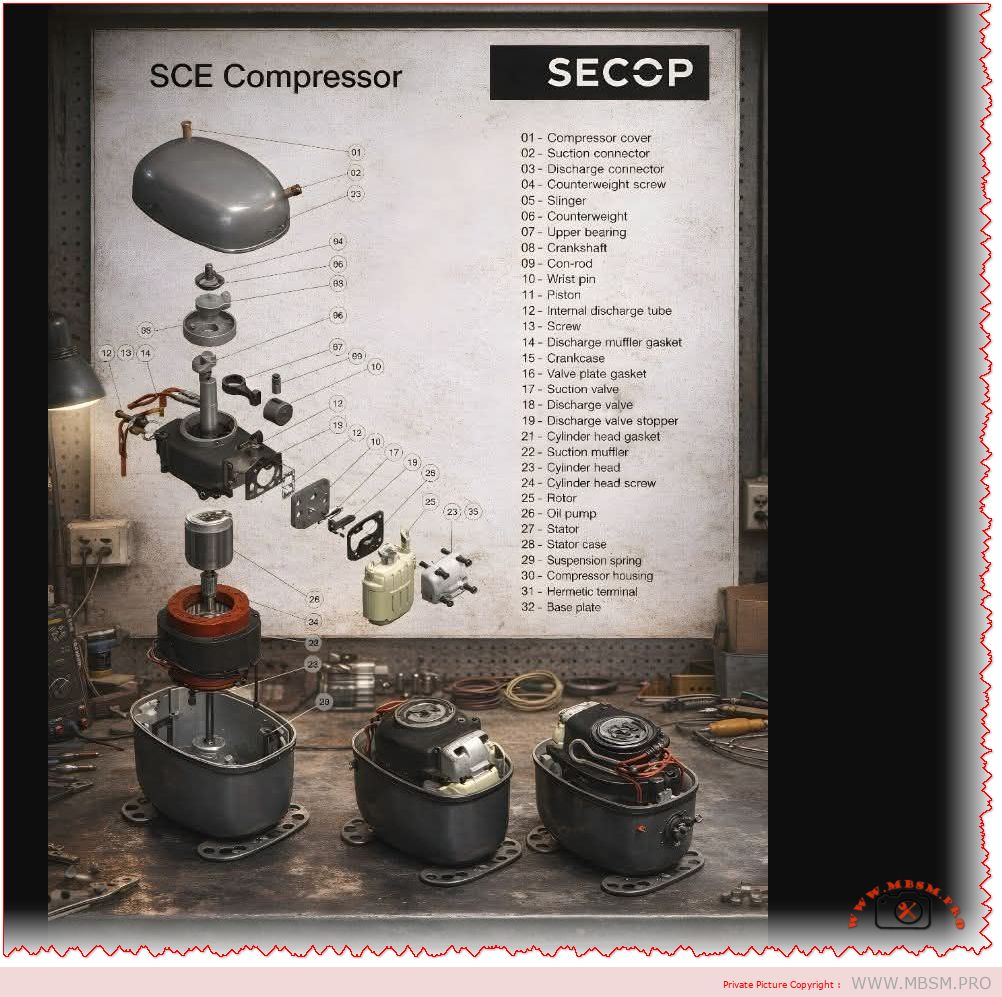
Inside the SECOP SCE Hermetic Compressor: A Complete Exploded View and Parts Identification Guide

For technicians, engineers, and procurement specialists in the commercial refrigeration industry, understanding the internal anatomy of a compressor is not just academic—it’s essential for efficient maintenance, accurate troubleshooting, and reliable sourcing of spare parts. The SECOP SCE series hermetic compressor is a cornerstone in many refrigeration systems, known for its durability and performance. This article provides a comprehensive, journalistic breakdown of its internal components using a detailed exploded view, serving as your definitive visual and technical guide.

Decoding the Exploded View: A Systematic Walkthrough

An exploded view diagram is more than just a parts list; it’s a roadmap to the machine’s soul. It shows how individual components interact within the sealed “hermetic” shell, where the motor and compressor are welded shut to protect against refrigerant and moisture. Let’s navigate the key assemblies revealed in the SCE compressor diagram.

1. The Core Compression Assembly

This is the heart of the compressor, where mechanical motion translates into refrigerant compression.

  • Piston (11) & Cylinder (Part of Crankcase 15): The piston moves within the cylinder bore, creating the vacuum and pressure cycles.
  • Crankshaft (8): Driven by the motor, its rotational motion is converted into the piston’s reciprocating motion via the connecting rod (9) and wrist pin (10).
  • Valve System: This critical assembly manages refrigerant flow. The suction valve (17) opens to draw in low-pressure gas. The discharge valve (18), held by its stopper (19), opens to release high-pressure gas into the discharge muffler.

2. The Electrical & Drive Assembly

Nestled beneath the compressor, this assembly powers the entire system.

  • Stator (27): The stationary part of the electric motor, containing copper windings, housed inside the stator case (28).
  • Rotor (25): Pressed onto the crankshaft (8), it rotates within the stator’s magnetic field.
  • Hermetic Terminal (31): The vital electrical pass-through that allows power cables to enter the sealed compressor housing without leaking refrigerant.

3. Structural & Ancillary Components

These parts provide support, balance, and necessary functionalities.

  • Compressor Housing (30): The iconic welded steel shell that contains all components.
  • Suspension Springs (29): Isolate vibrations, preventing noise and wear from transmitting to the refrigeration cabinet.
  • Oil Pump (26): Often a centrifugal type on the crankshaft, it ensures critical lubrication reaches the upper bearing (7) and other moving parts.
  • Counterweight (6): Balances the rotating assembly to minimize vibration, secured by a screw (4) and sometimes accompanied by a slinger (5).

Complete SECOP SCE Compressor Parts Reference Table

For quick reference and cross-referencing with part numbers, here is a complete table of the components identified in the exploded view:

Item No. Part Name Primary Function
01 Compressor Cover Protects internal parts, forms suction chamber
02 Suction Connector Inlet for low-pressure refrigerant gas
03 Discharge Connector Outlet for high-pressure refrigerant gas
04 Counterweight Screw Secures the counterweight to the crankshaft
05 Slinger Assists in oil distribution
06 Counterweight Balances rotating assembly to reduce vibration
07 Upper Bearing Supports the top of the rotating crankshaft
08 Crankshaft Converts motor rotation into piston movement
09 Connecting Rod Links the crankshaft to the piston
10 Wrist Pin Pivot point connecting piston and connecting rod
11 Piston Compresses refrigerant within the cylinder
12 Internal Discharge Tube Channels compressed gas to the muffler
13 Screw Fastens various components (e.g., muffler)
14 Discharge Muffler Gasket Seals the discharge muffler connection
15 Crankcase Main body housing cylinders and crankshaft
16 Valve Plate Gasket Seals between crankcase and valve plate
17 Suction Valve One-way valve for refrigerant intake
18 Discharge Valve One-way valve for refrigerant outlet
19 Discharge Valve Stopper Limits discharge valve movement
21 Cylinder Head Gasket Seals the cylinder head
22 Suction Muffler Reduces noise from suction gas pulsation
23 Cylinder Head Covers the cylinder, part of compression chamber
24 Cylinder Head Screw Secures the cylinder head
25 Rotor Rotating part of the electric motor
26 Oil Pump Circulates oil for lubrication
27 Stator Stationary electromagnetic part of the motor
28 Stator Case Holds and positions the stator
29 Suspension Spring Vibration isolation mounting
30 Compressor Housing Main hermetic (sealed) outer shell
31 Hermetic Terminal Electrical connection into sealed housing
32 Base Plate Foundation for internal assembly mounts

Why This Knowledge Matters for Your Business

Whether you’re a technician diagnosing a faulty discharge valve or a sourcing manager looking for a genuine SECOP crankshaft, this visual guide empowers you with precision. Correct part identification:

  • Reduces Downtime: Enables faster, accurate diagnosis.
  • Ensures Compatibility: Guarantees replacement parts match the exact SCE model specifications.
  • Promotes Effective Communication: Allows clear reference between teams, suppliers, and clients.


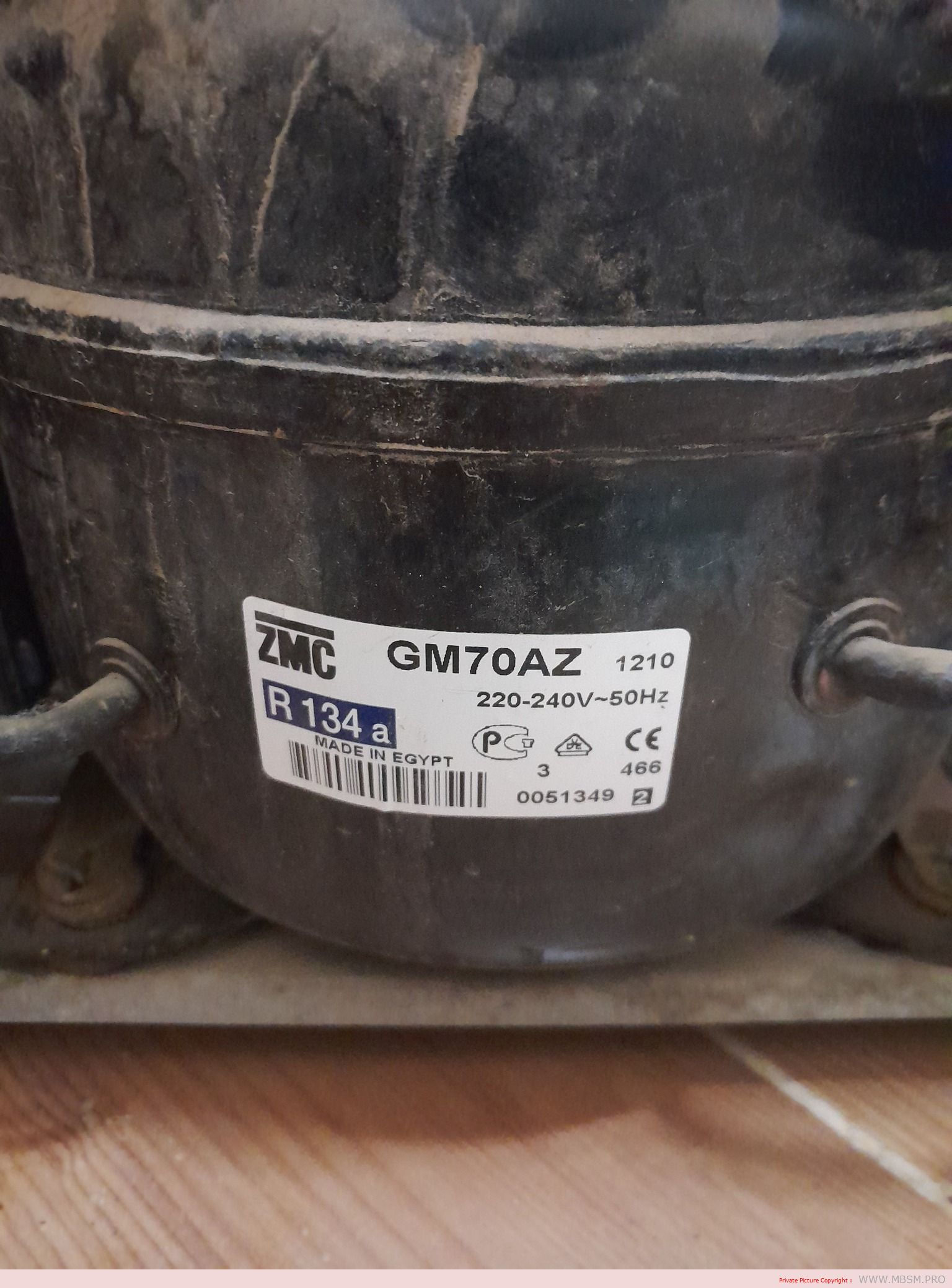
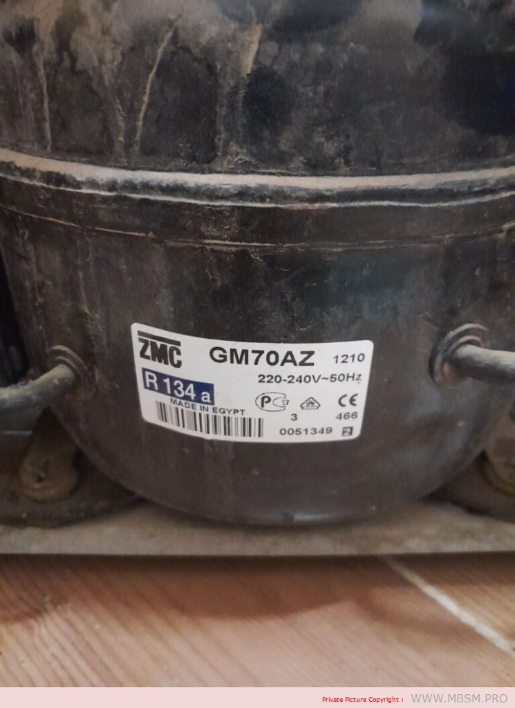
Mbsm.pro, Compressor, GM70AZ, 1/5 hp, ZMC, Cooling, R134a, 150 W, 1.3 A, 1Ph 220‑240V 50Hz, LBP capacity, RSIR, −30°C to −10°C

Le compresseur hermétique ZMC GM70AZ, visible sur l’étiquette de la photo, est un modèle fonctionnant au réfrigérant R134a, conçu pour les applications à basse pression d’aspiration dans le froid ménager. Fabriqué en Égypte par Misr Compressor Manufacturing Co. (ZMC), il cible les réfrigérateurs et congélateurs domestiques alimentés en 220–240 V, 50 Hz, très répandus en Afrique du Nord et au Moyen‑Orient.

Caractéristiques techniques essentielles

Le GM70AZ appartient à la famille de compresseurs LBP (Low Back Pressure), avec une plage d’évaporation typique d’environ −30 °C à −10 °C adaptée au froid négatif. Il fonctionne au réfrigérant R134a, avec un refroidissement du moteur par convection statique et une alimentation monophasée 220–240 V, 50 Hz comme indiqué sur l’étiquette.

Ce compresseur offre une puissance de l’ordre de 1/5 HP, ce qui le positionne pour des réfrigérateurs et congélateurs ménagers de petite à moyenne capacité. Il est fourni avec des connexions brasées pour aspiration, refoulement et process, ce qui facilite son intégration dans les circuits frigorifiques standards des fabricants et des ateliers de maintenance.

Tableau – Données techniques typiques ZMC E/GM70AZ

Paramètre Valeur indicative
Modèle GM70AZ / EGM70AZ 
Réfrigérant R134a 
Application LBP (basse pression d’aspiration) 
Plage de Te −30 °C à −10 °C 
Tension / fréquence 220–240 V ~ 50 Hz, 1 Ph 
Type de compresseur Hermétique à piston (reciprocating) 
Refroidissement compresseur Statique 
Domaine d’utilisation typique Réfrigérateurs / congélateurs domestiques 

Enjeux pour le froid domestique

Les compresseurs GM70AZ et EGM70AZ s’inscrivent dans la stratégie industrielle de ZMC visant à fournir des compresseurs hermétiques compétitifs pour les fabricants de réfrigérateurs et les marchés de rechange. Grâce à leur compatibilité avec le R134a, ils restent courants dans les appareils existants, même si le secteur s’oriente progressivement vers des réfrigérants à plus faible GWP comme le R600a.

Pour les techniciens frigoristes, l’identification correcte du modèle et du gaz, comme on le voit clairement sur l’étiquette GM70AZ, est essentielle pour respecter les conditions de fonctionnement (tension, plage d’évaporation, type de détente capillaire) et garantir longévité et efficacité énergétique. Ce type de compresseur est largement utilisé dans les ateliers de service en Tunisie, en Égypte et dans la région MENA, où les pièces ZMC sont facilement disponibles.