AMS1117 Voltage Regulator

AMS1117 Voltage Regulator: Common Mistakes, Practical Guide, and Engineering Best Practices

Overview The AMS1117 family of linear voltage regulators (fixed and adjustable versions) is ubiquitous in electronics projects, embedded systems, and power-supply rails. Despite its popularity, technicians and hobbyists repeatedly make the same installation and design mistakes that cause overheating, instability, and premature failure. This article explains those common mistakes, gives engineering‑grade corrections, compares AMS1117 variants with alternatives, and supplies practical tables, values, and installation checklists you can use in a WordPress technical post.

Why AMS1117 Is Widely Used

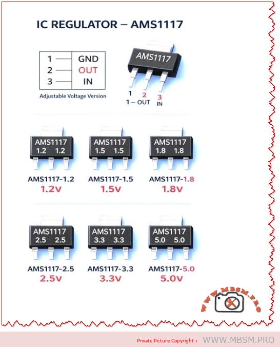
  • Simple three‑pin package (GND, OUT, IN) makes board layout straightforward.
  • Multiple fixed outputs available: 1.2V, 1.5V, 1.8V, 2.5V, 3.3V, 5.0V.
  • Low cost and broad availability for hobby and production use.
  • Good for low‑current rails (typical use up to ~1 A with proper thermal design).

Common Mistakes and Corrective Actions

Common Mistake Why it Fails Corrective Action
No input/output decoupling capacitors Regulator oscillates or output is noisy Place recommended capacitors: input 10 µF (electrolytic or tantalum) and output 10 µF low‑ESR close to pins
Ignoring thermal dissipation Device overheats under load; thermal shutdown Calculate power dissipation P=(VINVOUT)ILOAD; add heatsink or use switching regulator if P>1 W
Long traces between caps and pins Increased ESR/ESL causes instability Route short, wide traces; place caps within 5 mm of pins
Using AMS1117 for high step‑down Excessive wasted power and heat Use buck converter for large VIN–VOUT or high current
No reverse‑polarity or transient protection Device destroyed by spikes or reverse connection Add input TVS diode, series fuse, or reverse‑polarity MOSFET
Wrong capacitor type ESR too high or too low causing instability Use low‑ESR electrolytic or tantalum on output; ceramic + electrolytic combo on input
Expecting full 1 A without thermal design Device current limit or thermal shutdown Derate to 0.7–0.8 A unless heatsink and airflow provided

Practical Design Checklist (Quick Reference)

  • Select correct AMS1117 variant for required output voltage (1.2 / 1.5 / 1.8 / 2.5 / 3.3 / 5.0 V).
  • Calculate worst‑case dissipation: Pmax=(VIN,maxVOUT)Imax.
  • Choose caps: Input 10 µF low‑ESR; Output 10 µF low‑ESR; add 0.1 µF ceramic for high‑frequency decoupling.
  • Thermal plan: Heatsink area, copper pour, and airflow if Pmax>1 W.
  • Layout: Short traces, wide copper, thermal vias under package for SMD variants.
  • Protection: Input TVS, series fuse, reverse‑polarity protection.
  • Testing: Thermal imaging under full load; measure output ripple and transient response.

Thermal Calculation Example

  • Given: VIN = 12 V, VOUT = 5 V, ILOAD = 0.8 A
  • Dissipation: P=(125)0.8=5.6 W
  • Implication: 5.6 W requires substantial heatsinking; AMS1117 in a TO‑220 or SOT‑223 without heatsink will overheat. Consider switching regulator.

Comparison Table: AMS1117 vs. Common Alternatives

Attribute AMS1117 (Linear) LM2596 (Buck) LDO Modern (e.g., MIC5219)
Efficiency at 5 V out from 12 V in ~42% ~85–95% ~42–60%
Typical max current ~1 A (thermally limited) 3 A (switching) 500 mA–1 A
Output noise Low‑mid Higher switching noise Low
Board complexity Low Higher (inductor, diode, caps) Low
Thermal stress High for large VIN–VOUT Low Moderate
Best use case Small loads, simple designs High current, large step‑down Low‑noise low‑current rails

When to Choose AMS1117 (Use Cases)

  • Low‑power microcontroller rails (e.g., 3.3 V at < 300 mA).
  • Simple sensor boards where VIN is close to VOUT (small voltage drop).
  • Prototyping and low‑volume products where cost and simplicity matter.

When to Avoid AMS1117 (Alternatives)

  • High current (>1 A) or large VIN–VOUT difference — use a buck converter.
  • Battery‑powered designs where efficiency is critical — use switching regulator.
  • Very low noise analog rails — choose a precision LDO with low noise spec.

Layout and PCB Best Practices

  • Place caps within 2–5 mm of regulator pins.
  • Use wide input and output traces (or pour copper) to reduce voltage drop and improve heat spreading.
  • Add thermal vias under SMD packages to move heat to inner or bottom copper.
  • Keep sensitive analog traces away from the regulator’s hot copper and switching nodes (if present).
  • Label polarity clearly and include test points for VIN, VOUT, and GND.

Testing and Validation Steps

  1. No‑load test: Verify VOUT with no load; check for oscillation.
  2. Step‑load test: Apply sudden load changes and measure transient response.
  3. Thermal test: Run at maximum expected load for 30 minutes; measure case and PCB temps.
  4. Ripple test: Measure output ripple with oscilloscope; ensure within tolerance for your circuit.
  5. Fault test: Simulate short‑circuit and overvoltage to confirm protection behavior.

Common Failure Modes and Troubleshooting

  • Symptom: Output drops under load → Check thermal shutdown, insufficient input voltage, or current limit.
  • Symptom: Output noisy or oscillating → Check output capacitor ESR and placement.
  • Symptom: Device hot to touch → Check power dissipation calculation and add heatsink or switch to buck converter.
  • Symptom: No output → Check input presence, reverse polarity protection, and solder joints.

Engineering Notes and Practical Tips

  • Combine capacitors: a 0.1 µF ceramic in parallel with a 10 µF electrolytic gives best high‑ and low‑frequency performance.
  • Derate current: assume 70–80% of the absolute max in real designs unless thermal path is proven.
  • Use thermal simulation or simple hand calculations to size copper pour and heatsink.
  • Document expected VIN range and include transient protection if VIN can spike (e.g., automotive or industrial environments).

Focus Keyphrase

AMS1117 common mistakes thermal design decoupling capacitor layout oscillation protection buck alternative 1.2V 1.8V 3.3V 5V regulator

SEO Title

Mbsmpro.com, AMS1117 Voltage Regulator, Common Mistakes, Thermal Design, 1.2V–5.0V, Decoupling, Layout, Alternatives

Meta Description

Avoid overheating and instability with AMS1117 regulators. Learn the most common mistakes, thermal calculations, capacitor recommendations, PCB layout tips, and when to choose a buck converter instead.

Slug

ams1117-common-mistakes-thermal-design-decap-layout-alternatives

Tags

AMS1117, Voltage Regulator, LDO, Decoupling, Thermal Design, PCB Layout, Buck Converter, 3.3V, 5V, Mbsmgroup, Mbsm.pro, mbsmpro.com, mbsm, Electronics, Power Supply

Excerpt (first 55 words)

AMS1117 linear regulators are simple and cheap, but common mistakes—missing decoupling, poor thermal planning, and long traces—cause instability and overheating. This guide explains capacitor choices, power dissipation math, PCB layout rules, testing steps, and when to switch to a buck converter for efficiency and reliability.

AMS1117 Voltage Regulator mbsmpro


PDF , HVAC et Refrigeration Parts, Copper, Chemicals, Compressors, Controls, Coils, Fans & Motors, Electronics, Service Tools, Supplies

PDF , HVAC et Refrigeration Parts, Copper, Chemicals, Compressors, Controls, Coils, Fans & Motors, Electronics, Service Tools, Supplies


www.mbsm.pro , Practical Electronics for Inventors, Fourth Edition

Practical Electronics for Inventors, Fourth Edition

by: Paul Scherz, Dr. Simon Monk

Abstract: A fully updated, no-nonsense guide to electronics. Advance your electronics knowledge and gain the skills necessary to develop and construct your own functioning gadgets. Written by a pair of experienced engineers and dedicated hobbyists, Practical Electronics for Inventors, Fourth Edition, lays out the essentials and provides step-by-step instructions, schematics, and illustrations. Discover how to select the right components, design and build circuits, use microcontrollers and ICs, work with the latest software tools, and test and tweak your creations. This easy-to-follow book features new instruction on programmable logic, semiconductors, operational amplifiers, voltage regulators, power supplies, digital electronics, and more. Coverage includes: • Resistors, capacitors, inductors, and transformers • Diodes, transistors, and integrated circuits • Optoelectronics, solar cells, and phototransistors • Sensors, GPS modules, and touch screens • Op amps, regulators, and power supplies • Digital electronics, LCDs, and logic gates • Microcontrollers and prototyping platforms • Combinational and sequential programmable logic • DC motors, RC servos, and stepper motors • Microphones, audio amps, and speakers • Modular electronics and prototypes


Book Details

Title: Practical Electronics for Inventors, Fourth Edition

Publisher: McGraw-Hill Education: New York, Chicago, San Francisco, Athens, London, Madrid, Mexico City, Milan, New Delhi, Singapore, Sydney, Toronto

Copyright / Pub. Date: 2016 McGraw-Hill Education

ISBN: 9781259587542

Authors:

Paul Scherz is a Systems Operation Manager who received his B.S. in physics from the University of Wisconsin. He is an inventor/hobbyist in electronics, an area he grew to appreciate through his experience at the University’s Department of Nuclear Engineering and Engineering Physics and Department of Plasma Physics.

Dr. Simon Monk has a bachelor’s degree in cybernetics and computer science and a Ph.D. in software engineering. He spent several years as an academic before he returned to industry, co-founding the mobile software company Momote Ltd. He has been an active electronics hobbyist since his early teens and is a full-time writer on hobby electronics and open-source hardware. Dr. Monk is author of numerous electronics books, including Programming Arduino, Hacking Electronics, and Programming the Raspberry Pi.

Description: A fully updated, no-nonsense guide to electronics. Advance your electronics knowledge and gain the skills necessary to develop and construct your own functioning gadgets. Written by a pair of experienced engineers and dedicated hobbyists, Practical Electronics for Inventors, Fourth Edition, lays out the essentials and provides step-by-step instructions, schematics, and illustrations. Discover how to select the right components, design and build circuits, use microcontrollers and ICs, work with the latest software tools, and test and tweak your creations. This easy-to-follow book features new instruction on programmable logic, semiconductors, operational amplifiers, voltage regulators, power supplies, digital electronics, and more. Coverage includes: • Resistors, capacitors, inductors, and transformers • Diodes, transistors, and integrated circuits • Optoelectronics, solar cells, and phototransistors • Sensors, GPS modules, and touch screens • Op amps, regulators, and power supplies • Digital electronics, LCDs, and logic gates • Microcontrollers and prototyping platforms • Combinational and sequential programmable logic • DC motors, RC servos, and stepper motors • Microphones, audio amps, and speakers • Modular electronics and prototypes

Table of Contents

A. ABOUT THE AUTHORS
B. PREFACE
C. ACKNOWLEDGMENTS
1. Introduction to Electronics
2. Theory
3. Basic Electronic Circuit Components
4. Semiconductors
5. Optoelectronics
6. Sensors
7. Hands-on Electronics
8. Operational Amplifiers
9. Filters
10. Oscillators and Timers
11. Voltage Regulators and Power Supplies
12. Digital Electronics
13. Microcontrollers
14. Programmable Logic
15. Motors
16. Audio Electronics
17. Modular Electronics
A. Power Distribution and Home Wiring
B. Error Analysis
C. Useful Facts and Formulas

Tools & Media

figure (1 036)
table (64)

Expanded Table of Contents

A. ABOUT THE AUTHORS
PREFACE PRELIMINARIES
ABOUT THE TECHNICAL EDITORS
B. PREFACE
PREFACE PRELIMINARIES
Notes about the Fourth Edition
C. ACKNOWLEDGMENTS
1. Introduction to Electronics
CHAPTER PRELIMINARIES
2. Theory
CHAPTER PRELIMINARIES
Theory of Electronics
Electric Current
Voltage
A Microscopic View of Conduction (for Those Who Are Interested)
Resistance, Resistivity, Conductivity
Insulators, Conductors, and Semiconductors
Heat and Power
Thermal Heat Conduction and Thermal Resistance
Wire Gauges
Grounds
Electric Circuits
Ohm’s Law and Resistors
Voltage and Current Sources
Measuring Voltage, Current, and Resistance
Combining Batteries
Open and Short Circuits
Kirchhoff’s Laws
Superposition Theorem
Thevenin’s and Norton’s Theorems
AC Circuits
AC and Resistors, RMS Voltage, and Current
Mains Power
Capacitors
Inductors
Modeling Complex Circuits
Complex Numbers
Circuit with Sinusoidal Sources
Power in AC Circuits (Apparent Power, Real Power, Reactive Power)
Thevenin’s Theorem in AC Form
Resonant Circuits
Lecture on Decibels
Input and Output Impedance
Two-Port Networks and Filters
Transient Circuits
Circuits with Periodic Nonsinusoidal Sources
Nonperiodic Sources
SPICE
3. Basic Electronic Circuit Components
CHAPTER PRELIMINARIES
Wires, Cables, and Connectors
Batteries
Switches
Relays
Resistors
Capacitors
Inductors
Transformers
Fuses and Circuit Breakers
4. Semiconductors
CHAPTER PRELIMINARIES
Semiconductor Technology
Diodes
Transistors
Thyristors
Transient Voltage Suppressors
Integrated Circuits
5. Optoelectronics
CHAPTER PRELIMINARIES
A Little Lecture on Photons
Lamps
Light-Emitting Diodes
Photoresistors
Photodiodes
Solar Cells
Phototransistors
Photothyristors
Optoisolators
Optical Fiber
6. Sensors
CHAPTER PRELIMINARIES
General Principles
Temperature
Proximity and Touch
Movement, Force, and Pressure
Chemical
Light, Radiation, Magnetism, and Sound
GPS
7. Hands-on Electronics
CHAPTER PRELIMINARIES
Safety
Constructing Circuits
Multimeters
Oscilloscopes
The Electronics Laboratory
8. Operational Amplifiers
CHAPTER PRELIMINARIES
Operational Amplifier Water Analogy
How Op Amps Work (The “Cop-Out” Explanation)
Theory
Negative Feedback
Positive Feedback
Real Kinds of Op Amps
Op Amp Specifications
Powering Op Amps
Some Practical Notes
Voltage and Current Offset Compensation
Frequency Compensation
Comparators
Comparators with Hysteresis
Using Single-Supply Comparators
Window Comparator
Voltage-Level Indicator
Instrumentation Amplifiers
Applications
9. Filters
CHAPTER PRELIMINARIES
Things to Know Before You Start Designing Filters
Basic Filters
Passive Low-Pass Filter Design
A Note on Filter Types
Passive High-Pass Filter Design
Passive Bandpass Filter Design
Passive Notch Filter Design
Active Filter Design
Integrated Filter Circuits
10. Oscillators and Timers
CHAPTER PRELIMINARIES
RC Relaxation Oscillators
The 555 Timer IC
Voltage-Controlled Oscillators
Wien-Bridge and Twin-T Oscillators
LC Oscillators (Sinusoidal Oscillators)
Crystal Oscillators
Microcontroller Oscillators
11. Voltage Regulators and Power Supplies
CHAPTER PRELIMINARIES
Voltage-Regulator ICs
A Quick Look at a Few Regulator Applications
The Transformer
Rectifier Packages
A Few Simple Power Supplies
Technical Points about Ripple Reduction
Loose Ends
Switching Regulator Supplies (Switchers)
Switch-Mode Power Supplies (SMPS)
Kinds of Commercial Power Supply Packages
Power Supply Construction
12. Digital Electronics
CHAPTER PRELIMINARIES
The Basics of Digital Electronics
Logic Gates
Combinational Devices
Logic Families
Powering and Testing Logic ICs
Sequential Logic
Counter ICs
Shift Registers
Analog/Digital Interfacing
Displays
Memory Devices
13. Microcontrollers
CHAPTER PRELIMINARIES
Basic Structure of a Microcontroller
Example Microcontrollers
Evaluation/Development Boards
Arduino
Interfacing with Microcontrollers
14. Programmable Logic
CHAPTER PRELIMINARIES
Programmable Logic
FPGAs
ISE and the Elbert V2
The Elbert 2 Board
Downloads
Drawing Your FPGA Logic Design
Verilog
Describing Your FPGA Design in Verilog
Modular Design
Simulation
VHDL
15. Motors
CHAPTER PRELIMINARIES
DC Continuous Motors
Speed Control of DC Motors
Directional Control of DC Motors
RC Servos
Stepper Motors
Kinds of Stepper Motors
Driving Stepper Motors
Controlling the Driver with a Translator
A Final Word on Identifying Stepper Motors
16. Audio Electronics
CHAPTER PRELIMINARIES
A Little Lecture on Sound
Microphones
Microphone Specifications
Audio Amplifiers
Preamplifiers
Mixer Circuits
A Note on Impedance Matching
Speakers
Crossover Networks
Simple ICs Used to Drive Speakers
Audible-Signal Devices
Miscellaneous Audio Circuits
17. Modular Electronics
CHAPTER PRELIMINARIES
There’s an IC for It
Breakout Boards and Modules
Plug-and-Play Prototyping
Open Source Hardware
A. Power Distribution and Home Wiring
APPENDIX PRELIMINARIES
Power Distribution
A Closer Look at Three-Phase Electricity
Home Wiring
Electricity in Other Countries
B. Error Analysis
APPENDIX PRELIMINARIES
Absolute Error, Relative Error, and Percent Error
Uncertainty Estimates
C. Useful Facts and Formulas
APPENDIX PRELIMINARIES
Greek Alphabet
Powers of 10 Unit Prefixes
Linear Functions (y = mx + b)
Quadratic Equation (y = ax2 + bx + c)
Exponents and Logarithms
Trigonometry
Complex Numbers
Differential Calculus
Integral Calculus

1

  1. https://www.amazon.com/Practical-Electronics-Inventors-Fourth-Scherz/dp/1259587541 [back]

www-mbsm-pro-Practical-Electronics-for-Inventors-Fourth-Edition1.png (273 KB)

www-mbsm-pro-Practical-Electronics-for-Inventors-Fourth-Edition1.png (239 KB)

www-mbsm-pro-Practical-Electronics-for-Inventors-Fourth-Edition1.png (239 KB)

www-mbsm-pro-Practical-Electronics-for-Inventors-Fourth-Edition1.png (239 KB)

www-mbsm-pro-Practical-Electronics-for-Inventors-Fourth-Edition2.png (121 KB)

www-mbsm-pro-Practical-Electronics-for-Inventors-Fourth-Edition2.png (111 KB)

www-mbsm-pro-Practical-Electronics-for-Inventors-Fourth-Edition2.png (111 KB)

www-mbsm-pro-Practical-Electronics-for-Inventors-Fourth-Edition2.png (111 KB)

www-mbsm-pro-Practical-Electronics-for-Inventors-Fourth-Edition3.png (146 KB)

www-mbsm-pro-Practical-Electronics-for-Inventors-Fourth-Edition3.png (134 KB)

www-mbsm-pro-Practical-Electronics-for-Inventors-Fourth-Edition3.png (134 KB)

www-mbsm-pro-Practical-Electronics-for-Inventors-Fourth-Edition3.png (134 KB)

www-mbsm-pro-Practical-Electronics-for-Inventors-Fourth-Edition4.png (193 KB)

www-mbsm-pro-Practical-Electronics-for-Inventors-Fourth-Edition4.png (178 KB)

www-mbsm-pro-Practical-Electronics-for-Inventors-Fourth-Edition4.png (178 KB)

www-mbsm-pro-Practical-Electronics-for-Inventors-Fourth-Edition4.png (178 KB)