Mbsm.pro, Compressor, Huaguang, asq80hg, Q series, 800 w, Hbp, r134a, 1/4 hp, cooling Aplication

Huaguang ASQ80HG Compressor: A Reliable Solution for Modern Refrigeration Systems
The Huaguang ASQ80HG compressor is a high-performance refrigeration component from the renowned Q Series , designed to meet the demands of modern cooling systems. With its compatibility with R134a refrigerant , high back-pressure (HBP) capability, and energy-efficient design, this compressor is an excellent choice for both domestic and commercial applications. Below, we explore its specifications, features, applications, and comparative analysis, supported by a detailed table.
Key Specifications
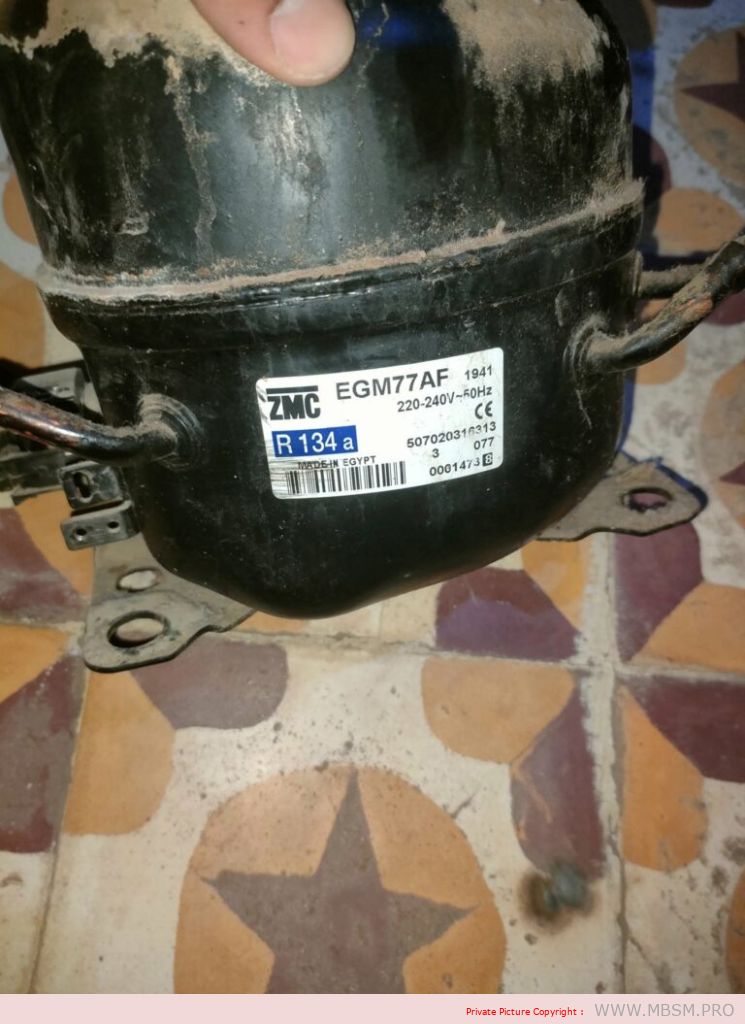
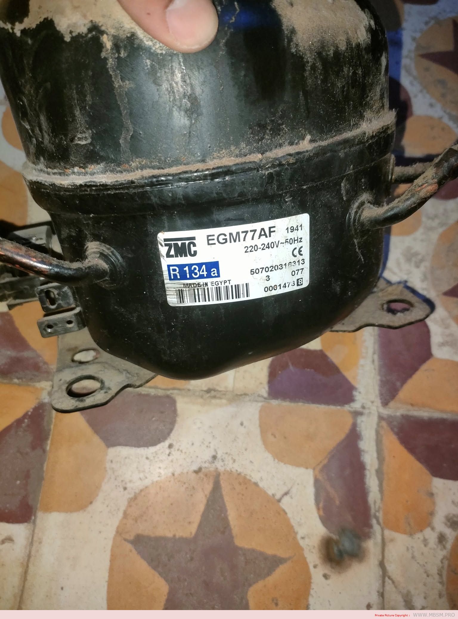
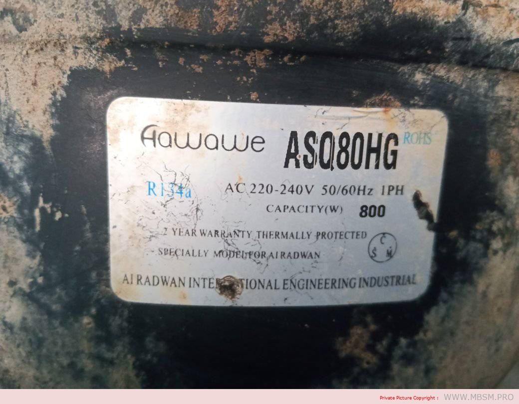
- Model : ASQ80HG
- Series : Q Series
- Power Input : 800W
- Horsepower : 1/4 HP (approximately 0.186 kW)
- Refrigerant : R134a
- Voltage/Frequency : 220-240V / 50Hz
- Application Type : High Back Pressure (HBP)
Overview of Features
The Huaguang ASQ80HG compressor is engineered for efficiency, durability, and environmental sustainability. Its compatibility with R134a refrigerant , a non-ozone-depleting gas, ensures compliance with global environmental standards. With an input power of 800W , it strikes a balance between performance and energy consumption, making it cost-effective for long-term use.
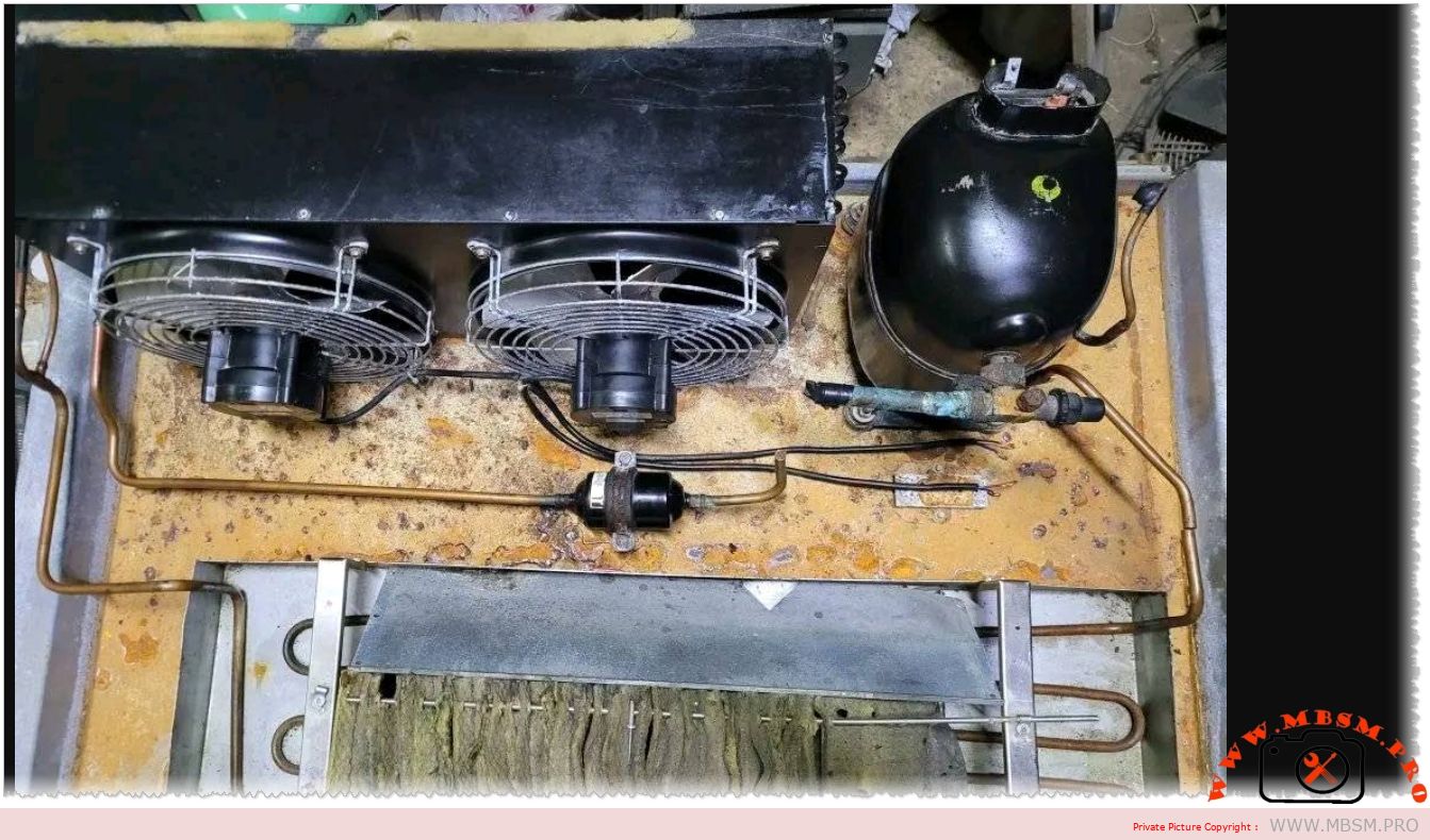
The high back-pressure (HBP) capability allows the compressor to maintain stable cooling in systems where evaporator pressures are relatively high, such as in freezers, display coolers, and other medium-temperature refrigeration setups.
Applications
The versatility of the ASQ80HG makes it suitable for a wide range of cooling applications, including:
- Domestic Refrigerators/Freezers : Ideal for home use due to its compact size and energy efficiency.
- Display Coolers : Perfect for retail environments requiring product visibility while maintaining low temperatures.
- Small-Scale Industrial Cooling : Suitable for systems demanding precise temperature control without heavy-duty cooling requirements.
- Cold Storage Units : Effective in maintaining consistent temperatures for perishable goods.
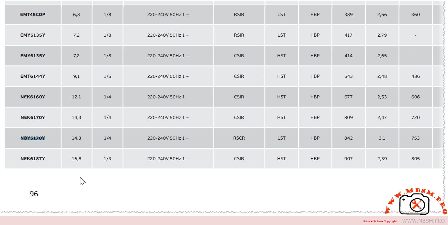
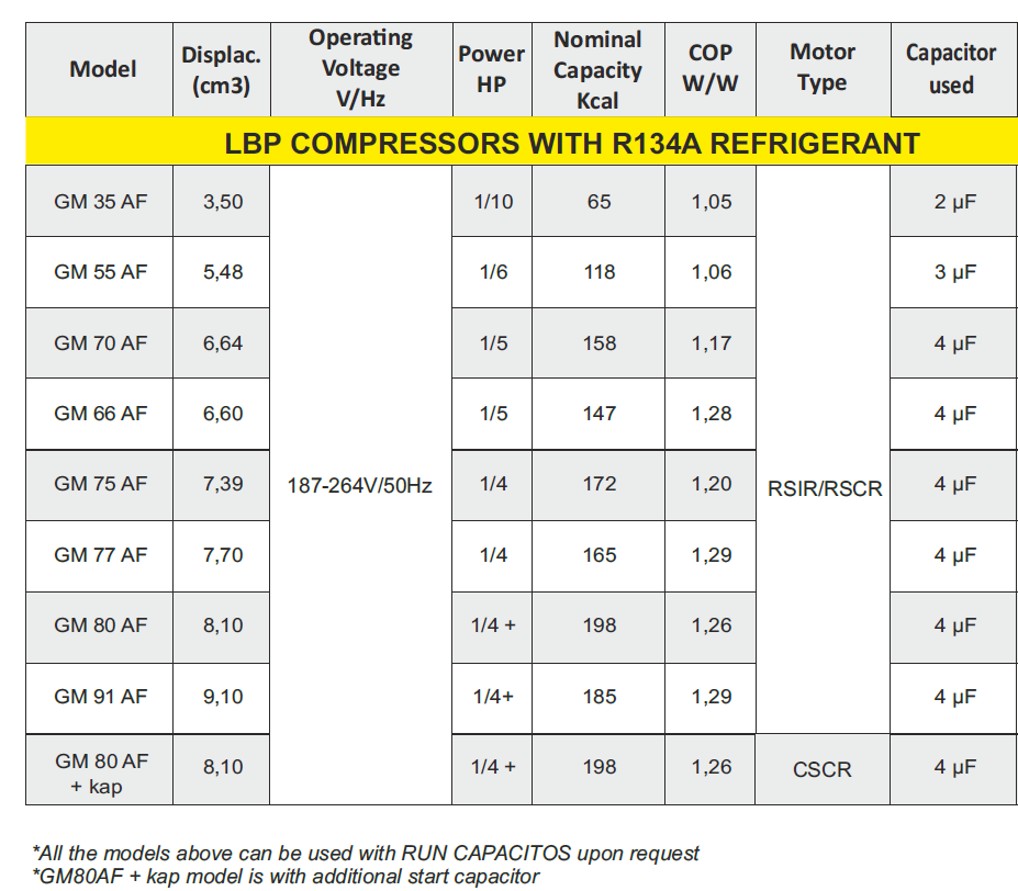
Comparative Table of Huaguang Compressors
Below is a comparative analysis of the Huaguang ASQ80HG with similar models in the Q Series , highlighting its unique advantages.
Why Choose the Huaguang ASQ80HG?
- Energy Efficiency : The 800W power input ensures optimal performance while minimizing energy consumption, reducing operational costs.
- Environmental Friendliness : The use of R134a refrigerant ensures compliance with global environmental regulations, as it does not contribute to ozone depletion.
- High Back Pressure Capability : Designed for systems requiring stable cooling under high back-pressure conditions, making it ideal for freezers and display coolers.
- Compact Design : Its compact size makes it suitable for installations with limited space, such as small kitchens or retail displays.
- Durability : Built to withstand demanding operating conditions, ensuring longevity and reliable performance.
Installation and Maintenance Tips
To ensure the best performance and longevity of the Huaguang ASQ80HG , follow these guidelines:
- Electrical Compatibility : Verify that the voltage (220-240V) and frequency (50Hz) match your local power supply.
- Proper Refrigerant Charge : Use only R134a refrigerant to avoid system inefficiencies and potential damage.
- Regular Cleaning : Clean the condenser coils periodically to prevent overheating and ensure efficient operation.
- Professional Installation : Hire a certified technician for installation and maintenance to avoid errors and ensure optimal performance.
Conclusion
The Huaguang ASQ80HG compressor from the Q Series is a versatile, energy-efficient, and environmentally friendly solution for various refrigeration needs. Its compatibility with R134a refrigerant , combined with its high back-pressure capability , makes it a standout choice for both domestic and commercial applications. Whether you’re upgrading your refrigerator, installing a new cooling system, or managing a retail display cooler, the ASQ80HG offers dependable performance and excellent value.