Mbsm.pro, Table, starting, capacitors, compressor

table of single-phase start and run capacitors

▷ Starting and Running Capacitors Table

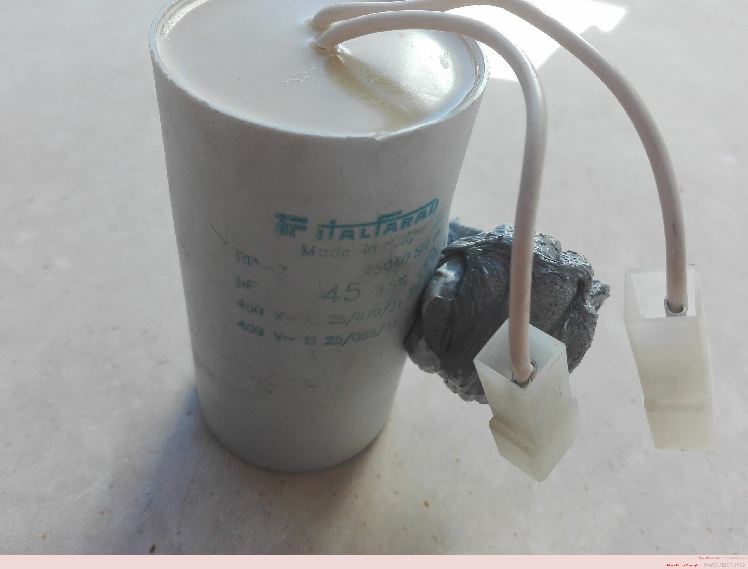
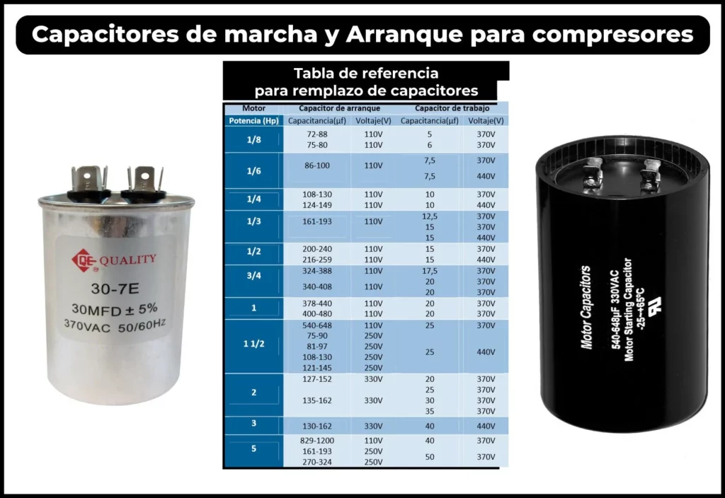
Do you need to replace a start or run  capacitor   and you don’t know which one the equipment has? In this post we will give you some tables of start and run capacitors so that you can access it when you need it.

The topic regarding the calculation of capacitors for single-phase compressors  is of great importance, because whoever is repairing needs to know when it is in poor condition and also what the replacement of the damaged part will be.

The technician who manipulates the equipment has to know that the new capacitor that he has bought to replace the old one must exactly meet the working voltage or greater than that of the original.

It is also important to highlight in this article that the compressor voltage has almost no relation to the capacitor voltage.

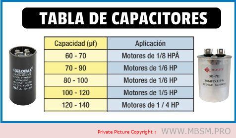
If you do not have the original capacitor data, you can approximate it using the following capacitor values ​​for single-phase motors that we present below.

They can be used as a guide or reference for selecting,  replacing capacitors when the exact values ​​are unknown.

Table of starting capacitors
for single-phase motors

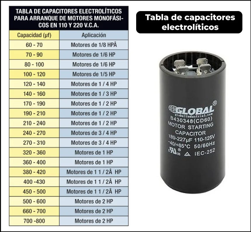
Table of Start and Run Capacitors
for Single Phase Capacitors

In this table, which is very similar to the previous one, I attach capacitor values ​​for single-phase motors.

both working and starting capacitors, this way you will have the most user-friendly information in a single image
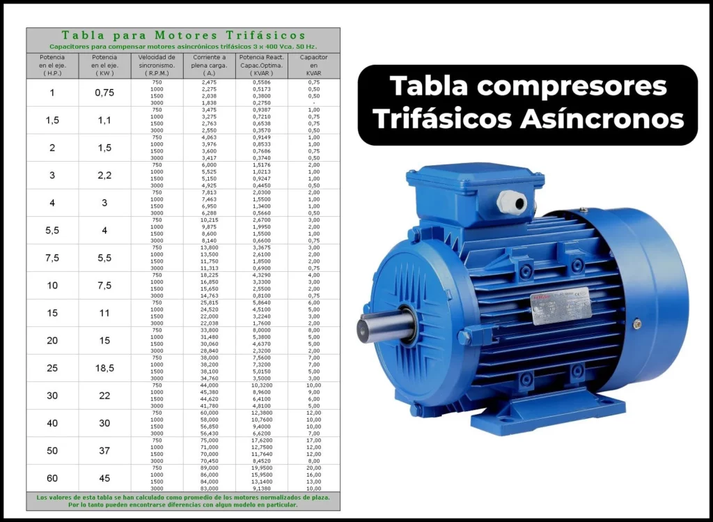
Capacitor Table for
Three-Phase Electric Motors

As a general rule, low-power three-phase electric motors have an operating voltage of 220 VD / 380 VY, but we must always make sure .

To do this, it is best to look at the motor’s nameplate. Where the voltages and connection will be indicated to know the type of  Capacitor they use.

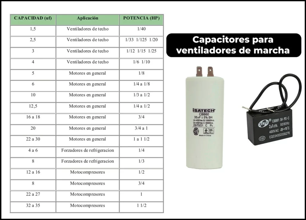
Fan run capacitor table

If you need to change a running or permanent fan capacitor, this table attached below can guide you to resolve the fault of the equipment you are repairing:

Understanding Starting Capacitors for Compressors: A Comprehensive Guide

Introduction
Starting capacitors play a crucial role in the efficient operation of compressors, especially in single-phase motors. They help generate the necessary starting torque and ensure smooth operation. This guide provides a detailed overview of starting capacitors, their importance, and how to select the right one for your compressor. We’ll also explore key specifications and troubleshooting tips to ensure optimal performance.


1. What is a Starting Capacitor?

A starting capacitor is an electrical component used in single-phase motors to create a phase shift, which generates the torque needed to start the motor. Without a starting capacitor, single-phase motors would struggle to start due to insufficient torque.


2. Key Functions of Starting Capacitors

  • Generate Starting Torque: Provides the necessary torque to start the compressor motor.
  • Phase Shift Creation: Creates a 90-degree phase shift to simulate a second phase in single-phase motors.
  • Smooth Operation: Ensures the motor starts smoothly without excessive current draw.

3. Table: Starting Capacitor Specifications for Compressors

Compressor Model Power (W) Voltage (V) Capacitance (µF) Max. Current (A) Release Current (A)
BSA15 150 230 10 1.55 1.6
BSA10 250 230 15 2.43 2.07
B10A19 300 230 20 3.0 2.56
B12A12 350 230 25 3.5 2.95
B16A13 500 230 30 5.15 4.85
B9A11 750 230 35 7.0 5.9

4. How to Calculate the Right Capacitor for Your Compressor

The capacitance of a starting capacitor is critical for optimal performance. Here’s a simple formula to calculate the required capacitance:

Formula:

C=P×1062πfV2cos⁡(ϕ)C=2πfV2cos(ϕ)P×106​

Where:

  • CC = Capacitance (in microfarads, µF)
  • PP = Motor power (in watts, W)
  • ff = Frequency (in hertz, Hz, typically 50 or 60 Hz)
  • VV = Voltage (in volts, V)
  • cos⁡(ϕ)cos(ϕ) = Power factor (typically 0.85 for motors)

Example Calculation:
For a motor with:

  • Power (PP) = 150 W
  • Voltage (VV) = 230 V
  • Frequency (ff) = 50 Hz
  • Power factor (cos⁡(ϕ)cos(ϕ)) = 0.85

C=150×1062π50×2302×0.85≈10.61 μFC=2π×50×2302×0.85150×106​≈10.61μF

In this case, a 10 µF capacitor would be ideal.


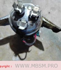
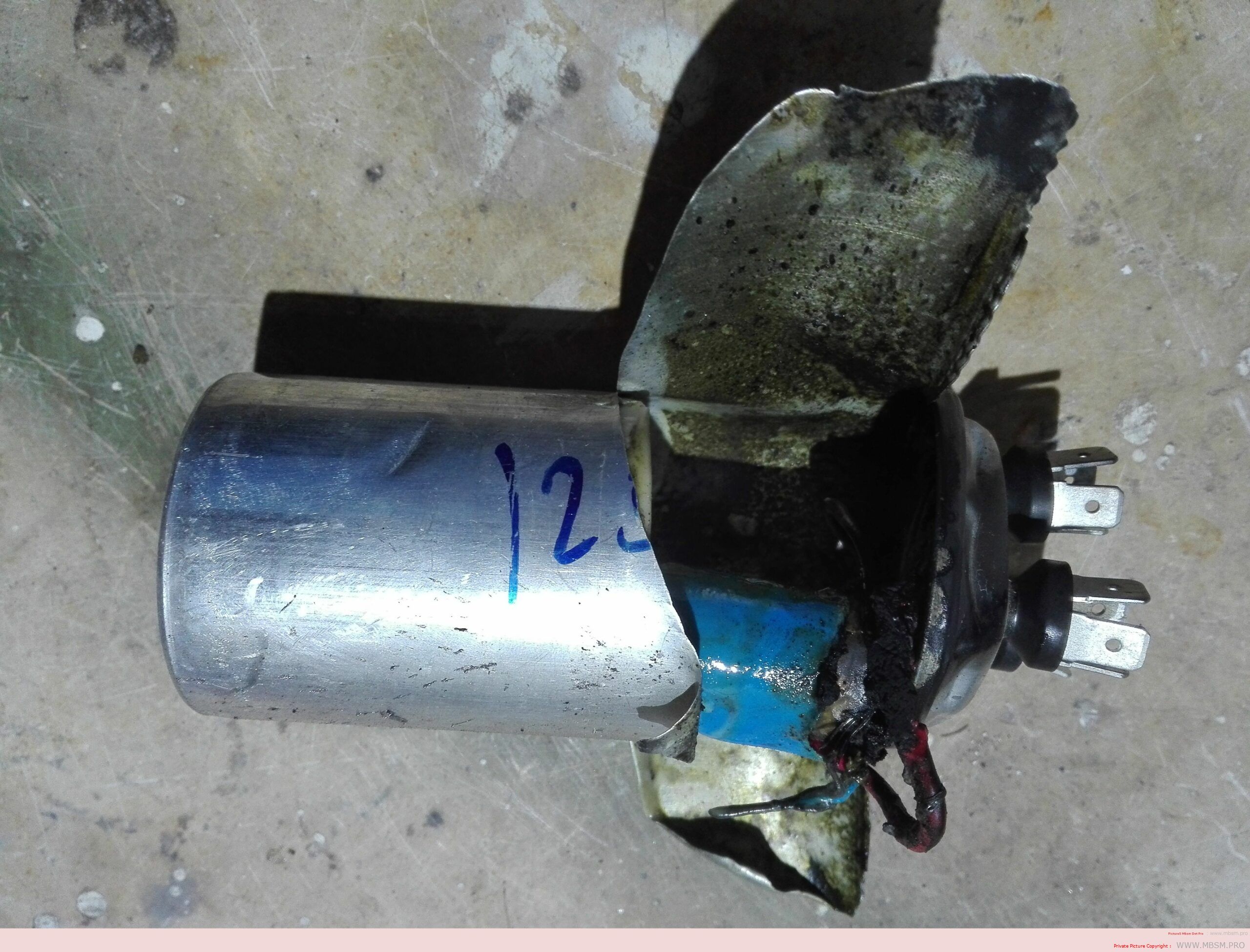
5. Common Issues with Starting Capacitors

  • Failed Capacitor: A faulty capacitor can prevent the motor from starting or cause it to overheat.
  • Incorrect Capacitance: Using a capacitor with the wrong capacitance can lead to insufficient torque or excessive current draw.
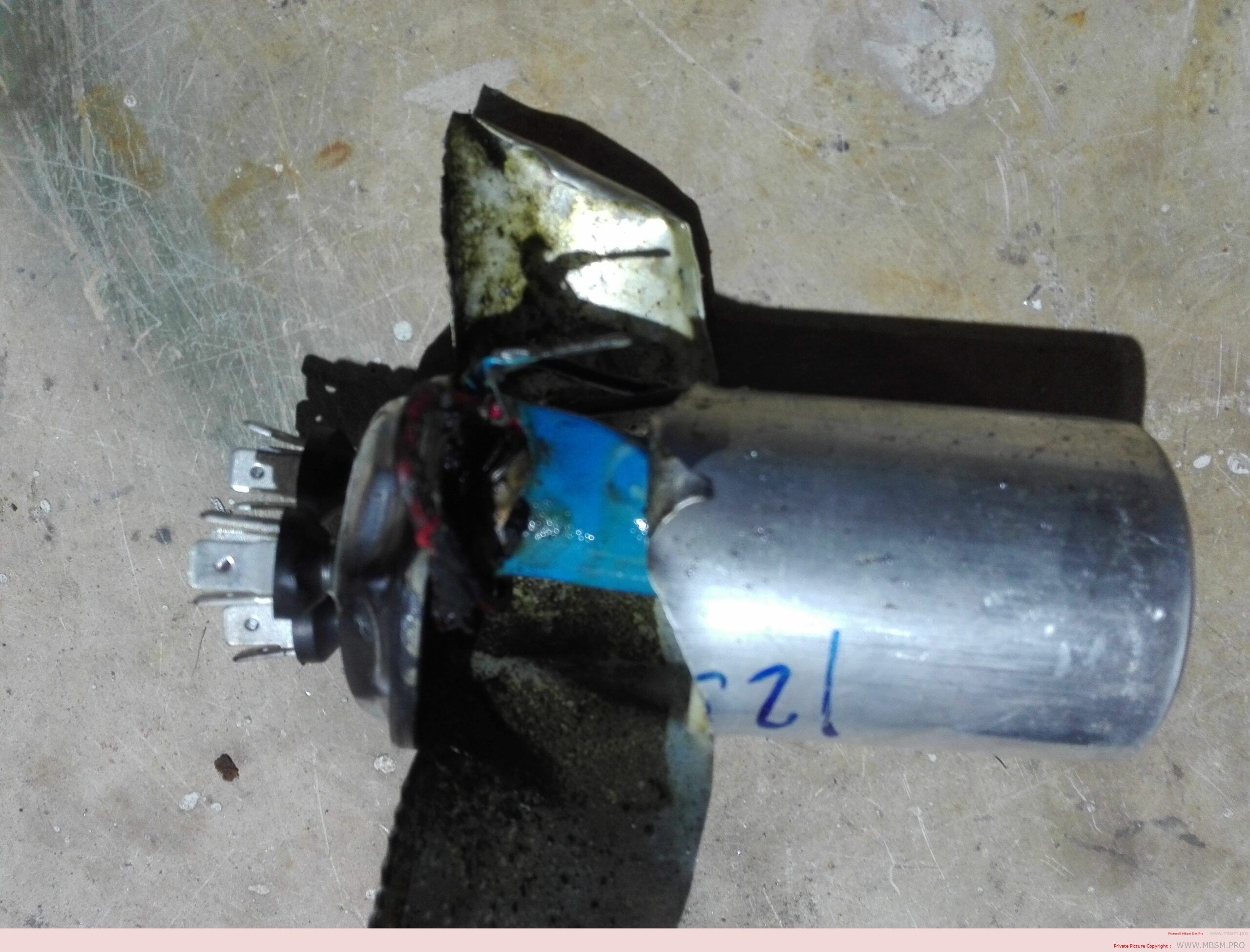
  • Overheating: Poor ventilation or excessive load can cause the capacitor to overheat and fail.

6. Troubleshooting Tips

  1. Check Continuity: Use a multimeter to test the capacitor for continuity. A failed capacitor will show no continuity.
  2. Measure Capacitance: Use a capacitance meter to ensure the capacitor’s value matches the required specifications.
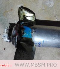
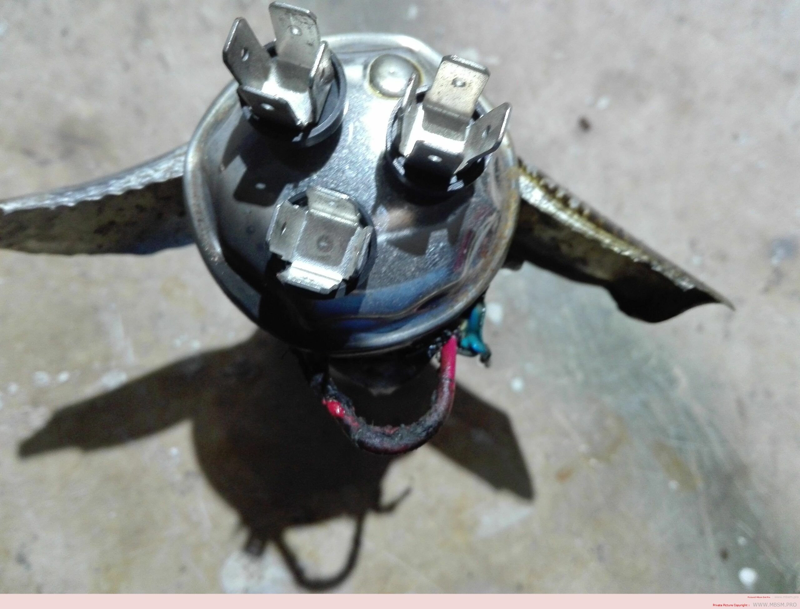
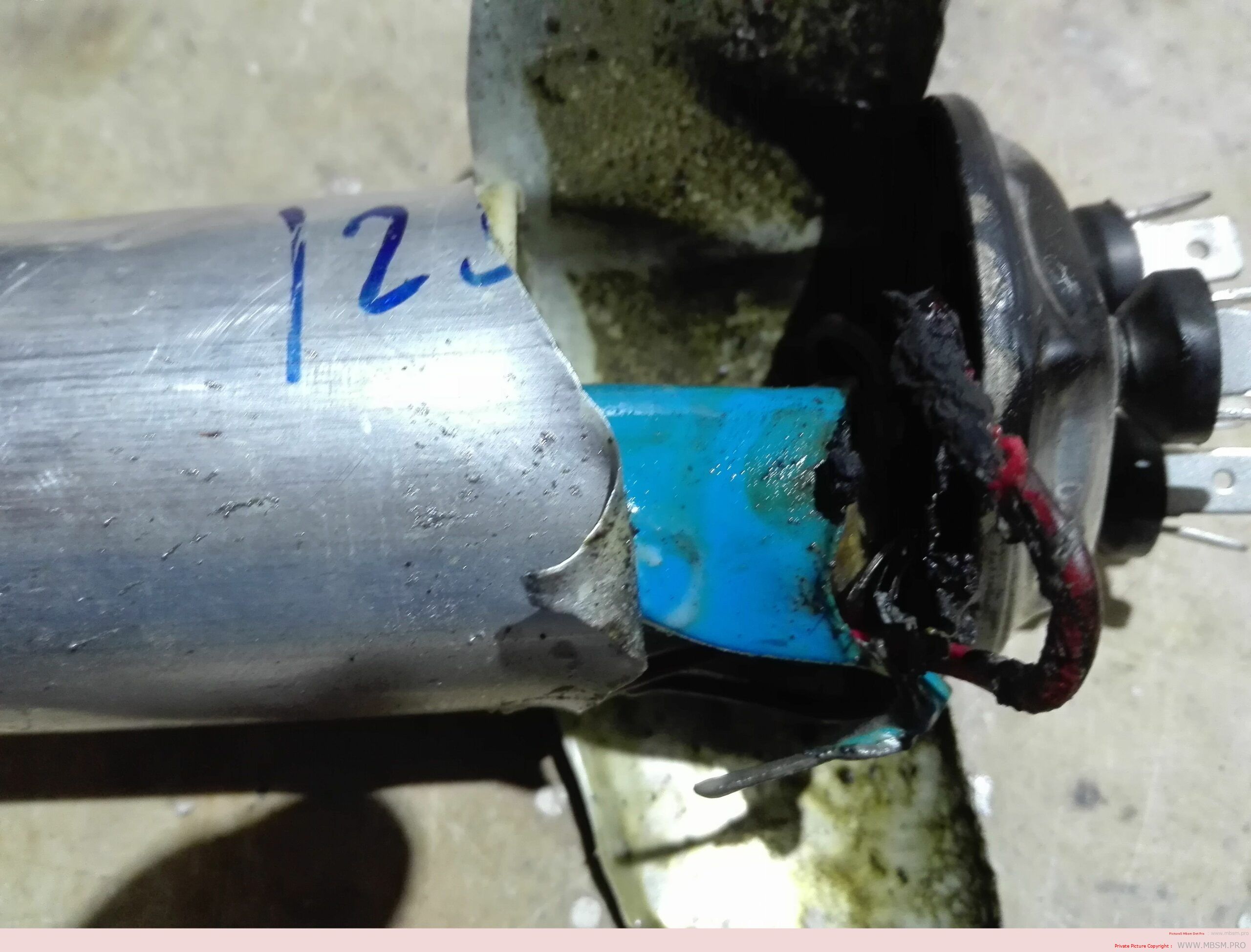
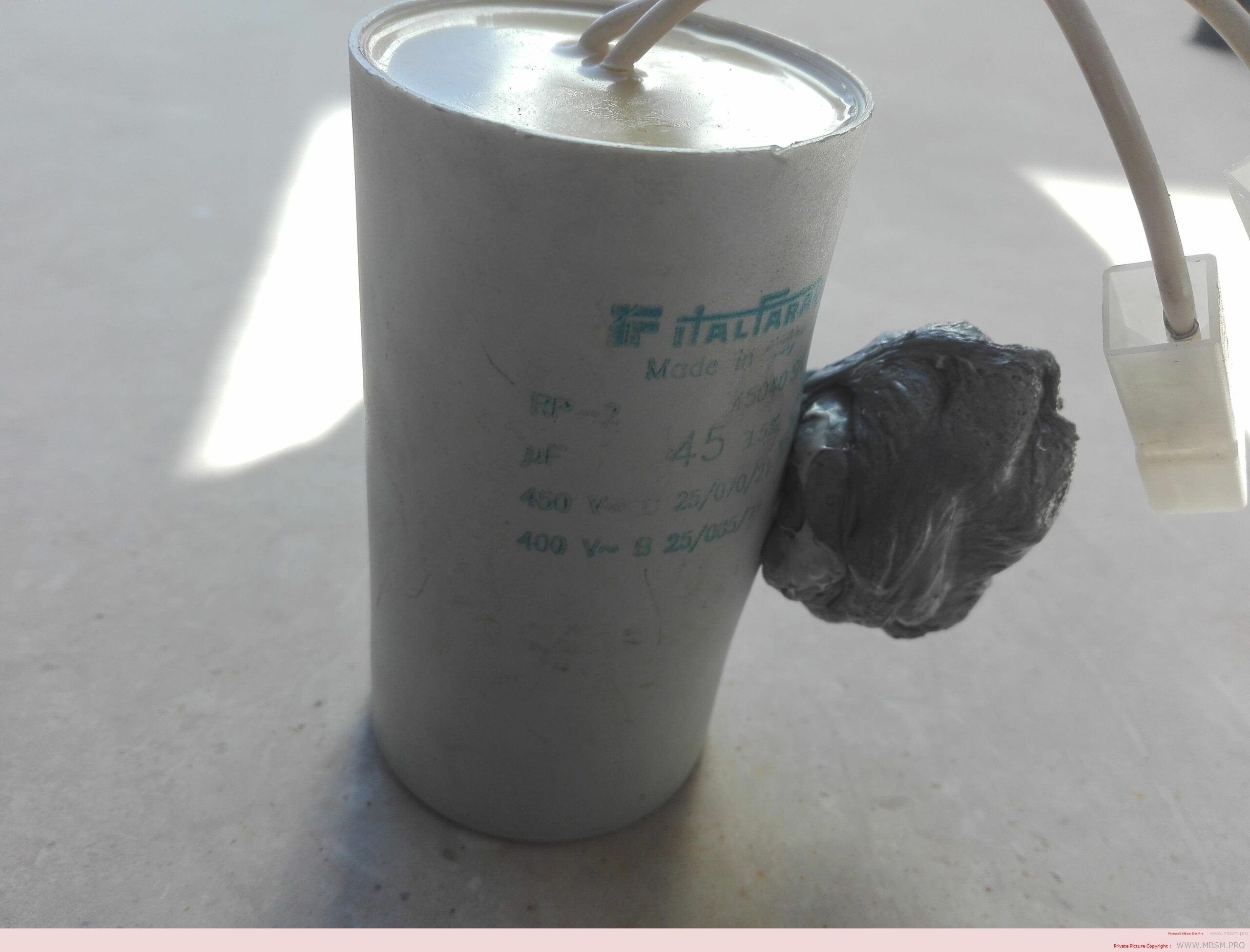
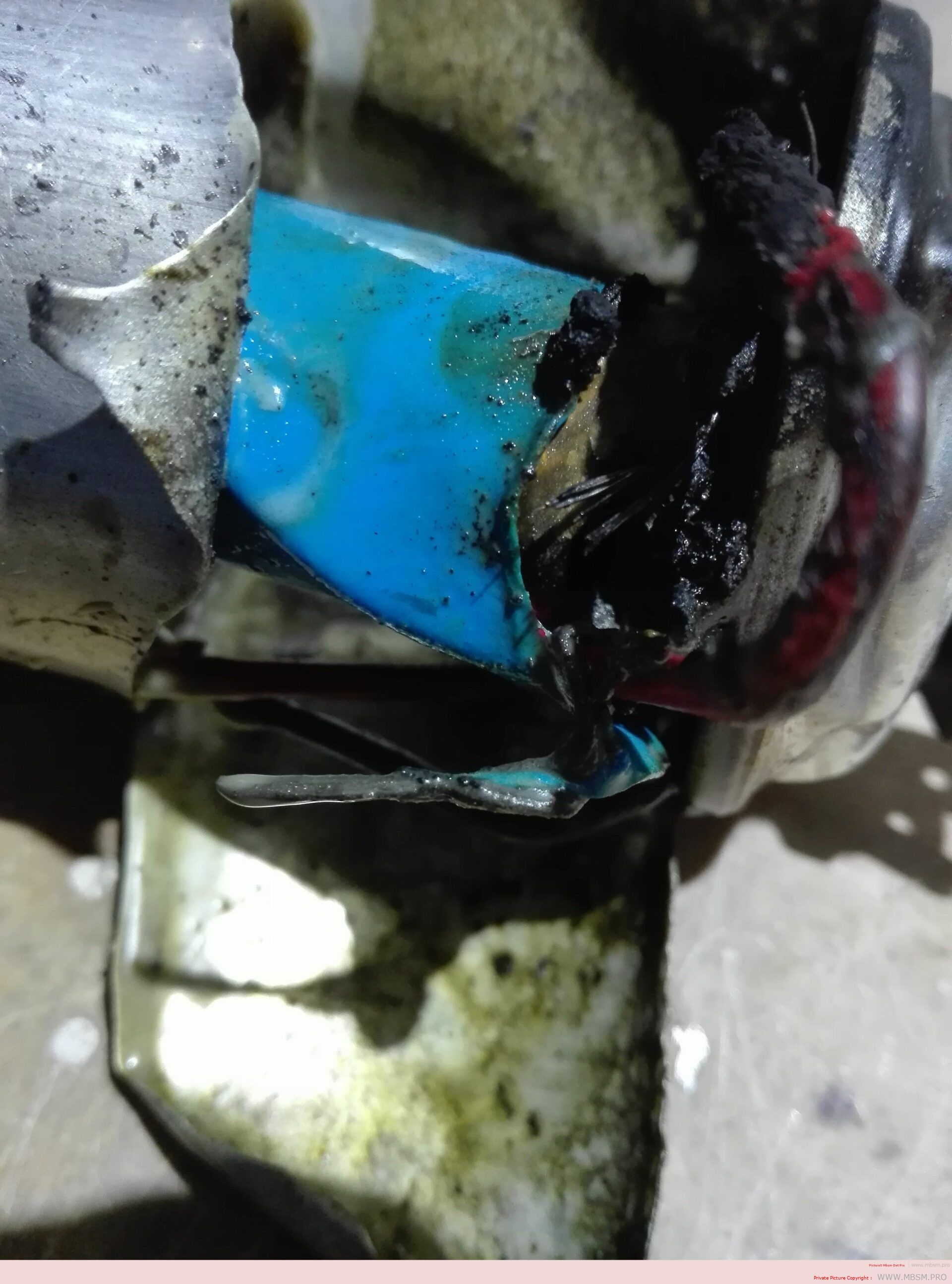
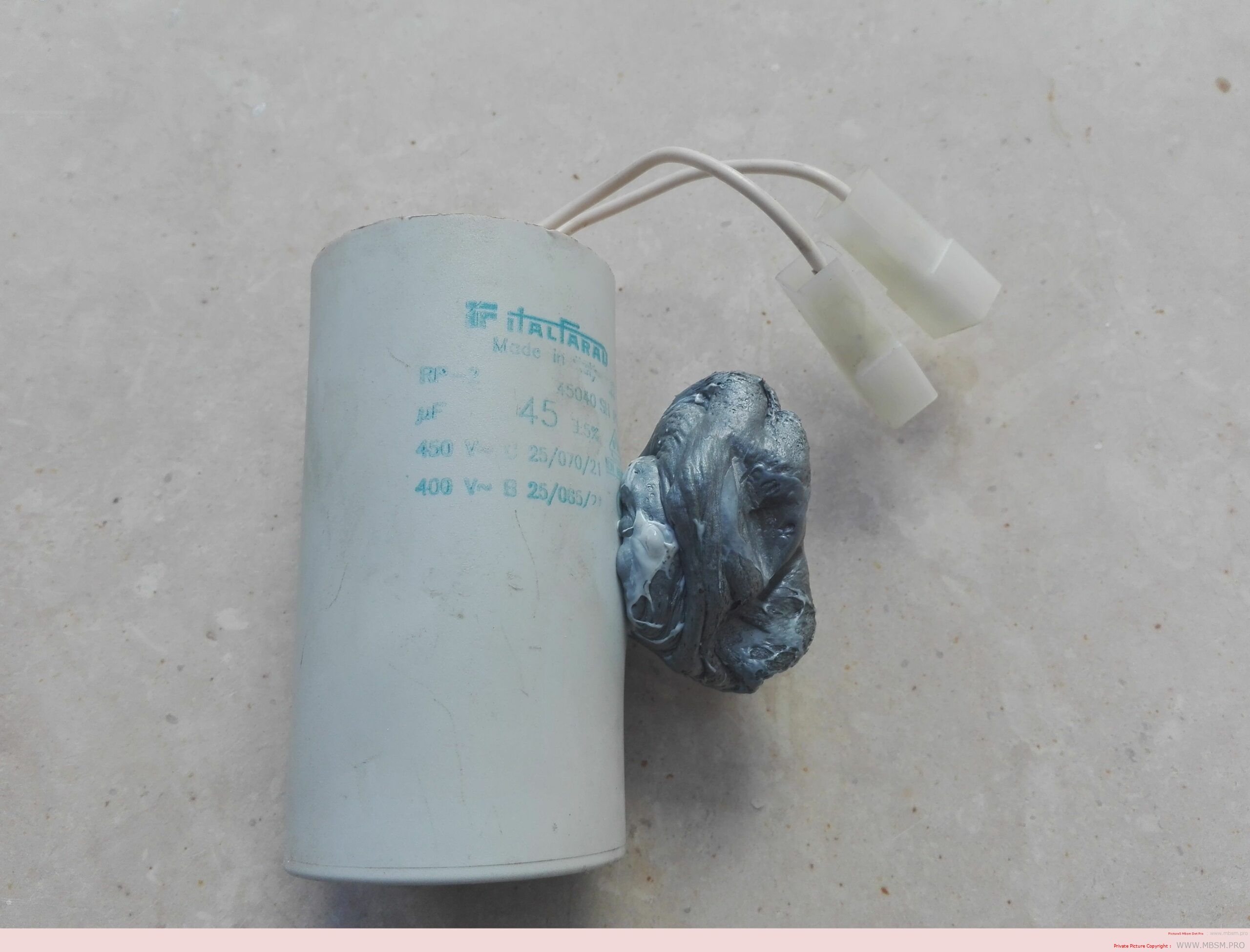
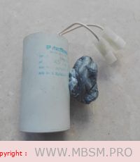
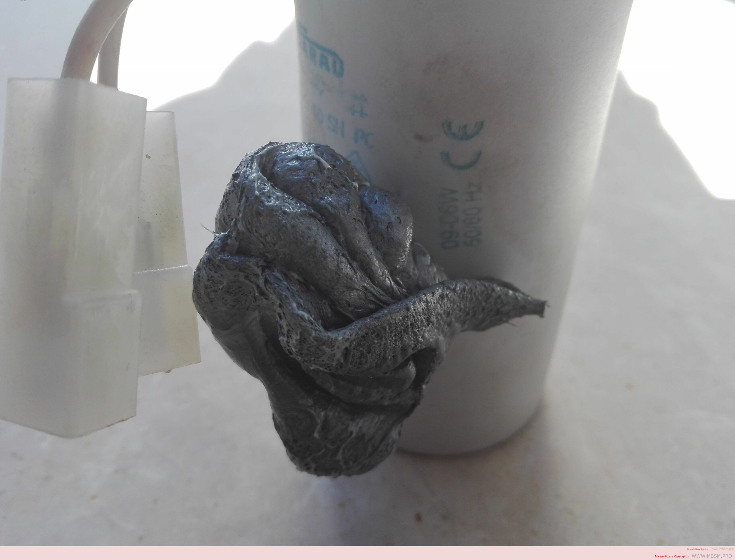
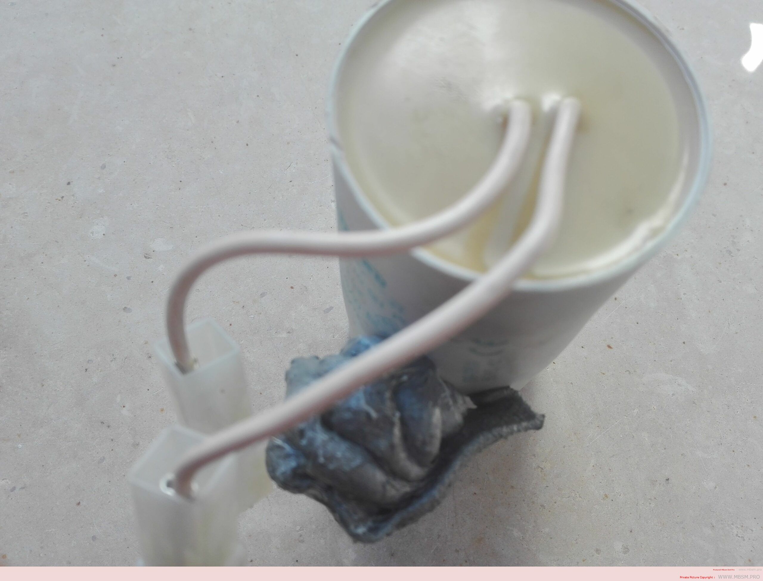
  3. Inspect for Physical Damage: Look for bulging, leaks, or burn marks on the capacitor, which indicate failure.
  4. Test Under Load: Ensure the compressor starts smoothly and does not draw excessive current during startup.

7. Advantages of Using the Right Starting Capacitor

  • Improved Motor Lifespan: Reduces stress on the motor during startup.
  • Energy Efficiency: Minimizes power consumption during operation.
  • Reliable Performance: Ensures consistent and reliable compressor operation.

8. Conclusion

Selecting the right starting capacitor for your compressor is essential for ensuring efficient and reliable operation. By understanding the specifications, calculating the correct capacitance, and performing regular maintenance, you can extend the lifespan of your compressor and avoid costly repairs.


www.mbsm.pro , when capacitor explodes , Pictures

A capacitor is a device used to store an electric charge, consisting of one or more pairs of conductors separated by an insulator.

Unexpectedly the electrolytic capacitors explodes with huge sound and sometime it smoke.

Get started , how to explode a capacitor ???
All capacitors have a maximum voltage and their destruction depends upon the internal construction. Explosions are understood only by delving into the internal construction of electrolytic capacitors – the primary culprit.

Most small value capacitors are simple sandwiches of conductor and insulator and when the voltage exceeds the dielectric strength of the insulation, they short out and burn, crack, pop, open, or smoke. Explosions are rare for these. Popping open is more likely. Their failure is self evident either visually or by failure to function in the circuit.

Most large value capacitors in order to be as small in physical size as possible, have to get the conductive plates of the capacitor as close together as possible and at the same time not so small that the voltage rating is impractical.

It is for this reason that the family of electrolytic capacitors was developed. The trick they use to get high capacity with small separations and reasonable voltage is that they use the “anodizing” of chemical electrolysis on one surface and a water based electrolyte for the other surface. Take one apart and see.

Notice that when a conductive metal is “anodized” by electrochemical process it turns into a dull film that is rather tough and is an insulator. This means that the actual conductive plate of the capacitor has this film entirely between itself and the other plate.

Then the other plate uses a trick too. There’s a water base solution soaked into a paper separator. Now if there was no water, the paper would be the dielectric of a normal capacitor separating the plates. But not here. Here the water has an alkali added to become a fair conductor. And as a liquid it soaks right into the surface structures of the capacitor. So it’s not the paper thickness at all – and not even the insulating surface on the other plate, but the inner recesses of the anodized surface that determine the dielectric distances.

So the operating voltage that a capacitor can tolerate depends upon how thick this anodized film is. And that is a function of it’s manufacture. Now there is a most useful characteristic that tells us we are nearing the max voltage, called leakage.

Here is a way you can check this out. Put in series, a test electrolytic capacitor (polarize it correctly), a variable power supply, a microammeter, and a 1 meg resistor (to limit and protect the meter). From zero as you increase the voltage there will be no current initially, then as you approach the spec op voltage, there will start a small leakage current. Since you have a limiting resistor here, you can increase the voltage without damage. continuing to increase the voltage discovers an increasing leakage current. It is a matter of practice how much safety you apply between the rating and the actual voltage of the circuit.

You can now see how it is that an electrolytic capacitor fails, it is not a voltage breakdown of the dielectric material, but the increase of leakage current that is troublesome. A rising leakage means heat which will boil the water and make steam – that’s the explosion process.

This is explosion as occasional failure of the few. But there is a more spectacular explosion process – it’s explosion by mistake – namely being installed backward. In such a case, the anodizing chemistry is reversed and rather rapidly, the anodized film starts to reverse, and quickly thins out at a weak spot in the rather large effective film area of the capacitor. Then we have short circuit currents and steam generation rather quickly. This sort of explosion usually fills the space (the casing or the whole room if exposed) with little shreads of aluminum foil and alkali soaked paper.

This insightful solution is most successful to achieve capacitors with large values in small spaces, but has a lot of lesser characteristics as the price to pay.

The worst limit, is storage. Electrolytic capacitors store very poorly, and the voltage rating can reduce substantially as the internal chemistry deteriorates. Some equipment manufacturers recommend that capacitors stored for a few years have their inner anodizing conditions restored by simply putting them to the spec voltage for a day to restore full spec.

At the least, if you replace capacitors with old stock, and it didn’t explode when power was restored, be aware that it may not reach it’s spec capacity value for a few hours. A capacitor in use will always be maintained by the voltage in the circuit you use it in.

When electrolytics are used without the circuit supplying a maintenance voltage to keep the anodized film that all depends upon, such as in speaker cross over applications that have no sustaining DC, then the values of the capacitor will deteriorate at least at storage rates, and if AC currents are substantial, even faster.

mbsm-dot-pro-capacitor-explodes- Pictures-A.jpg (4 MB)

mbsm-dot-pro-capacitor-explodes- Pictures-A.jpg (1 MB)

mbsm-dot-pro-capacitor-explodes- Pictures-A.jpg (1 MB)

mbsm-dot-pro-capacitor-explodes- Pictures-A.jpg (1 MB)

mbsm-dot-pro-capacitor-explodes- Pictures-B.jpg (3 MB)

mbsm-dot-pro-capacitor-explodes- Pictures-B.jpg (1 MB)

mbsm-dot-pro-capacitor-explodes- Pictures-B.jpg (1 MB)

mbsm-dot-pro-capacitor-explodes- Pictures-B.jpg (1 MB)

mbsm-dot-pro-capacitor-explodes- Pictures-C.jpg (3 MB)

mbsm-dot-pro-capacitor-explodes- Pictures-C.jpg (1 MB)

mbsm-dot-pro-capacitor-explodes- Pictures-C.jpg (1 MB)

mbsm-dot-pro-capacitor-explodes- Pictures-C.jpg (1 MB)

mbsm-dot-pro-capacitor-explodes- Pictures-D.jpg (3 MB)

mbsm-dot-pro-capacitor-explodes- Pictures-D.jpg (1 MB)

mbsm-dot-pro-capacitor-explodes- Pictures-D.jpg (1 MB)

mbsm-dot-pro-capacitor-explodes- Pictures-D.jpg (1 MB)

mbsm-dot-pro-capacitor-explodes- Pictures-F.jpg (2 MB)

mbsm-dot-pro-capacitor-explodes- Pictures-F.jpg (748 KB)

mbsm-dot-pro-capacitor-explodes- Pictures-F.jpg (748 KB)

mbsm-dot-pro-capacitor-explodes- Pictures-F.jpg (748 KB)

mbsm-dot-pro-capacitor-explodes- Pictures-E.jpg (3 MB)

mbsm-dot-pro-capacitor-explodes- Pictures-E.jpg (1 MB)

mbsm-dot-pro-capacitor-explodes- Pictures-E.jpg (1 MB)

mbsm-dot-pro-capacitor-explodes- Pictures-E.jpg (1 MB)

mbsm-dot-pro-capacitor-explodes- Pictures-G.jpg (2 MB)

mbsm-dot-pro-capacitor-explodes- Pictures-G.jpg (856 KB)

mbsm-dot-pro-capacitor-explodes- Pictures-G.jpg (856 KB)

mbsm-dot-pro-capacitor-explodes- Pictures-G.jpg (856 KB)

mbsm-dot-pro-capacitor-explodes- Pictures-H.jpg (2 MB)

mbsm-dot-pro-capacitor-explodes- Pictures-H.jpg (690 KB)

mbsm-dot-pro-capacitor-explodes- Pictures-H.jpg (690 KB)

mbsm-dot-pro-capacitor-explodes- Pictures-H.jpg (690 KB)

mbsm-dot-pro-capacitor-explodes- Pictures-I.jpg (2 MB)

mbsm-dot-pro-capacitor-explodes- Pictures-I.jpg (1 MB)

mbsm-dot-pro-capacitor-explodes- Pictures-I.jpg (1 MB)

mbsm-dot-pro-capacitor-explodes- Pictures-I.jpg (1 MB)

mbsm-dot-pro-capacitor-explodes- Pictures-J.jpg (2 MB)

mbsm-dot-pro-capacitor-explodes- Pictures-J.jpg (739 KB)

mbsm-dot-pro-capacitor-explodes- Pictures-J.jpg (739 KB)

mbsm-dot-pro-capacitor-explodes- Pictures-J.jpg (739 KB)