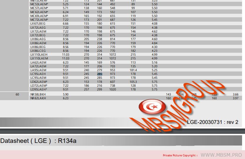
Do you need to replace a start or run capacitor and you don’t know which one the equipment has? In this post we will give you some tables of start and run capacitors so that you can access it when you need it.
The topic regarding the calculation of capacitors for single-phase compressors is of great importance, because whoever is repairing needs to know when it is in poor condition and also what the replacement of the damaged part will be.
The technician who manipulates the equipment has to know that the new capacitor that he has bought to replace the old one must exactly meet the working voltage or greater than that of the original.
It is also important to highlight in this article that the compressor voltage has almost no relation to the capacitor voltage.
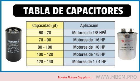
If you do not have the original capacitor data, you can approximate it using the following capacitor values for single-phase motors that we present below.
They can be used as a guide or reference for selecting, replacing capacitors when the exact values are unknown.
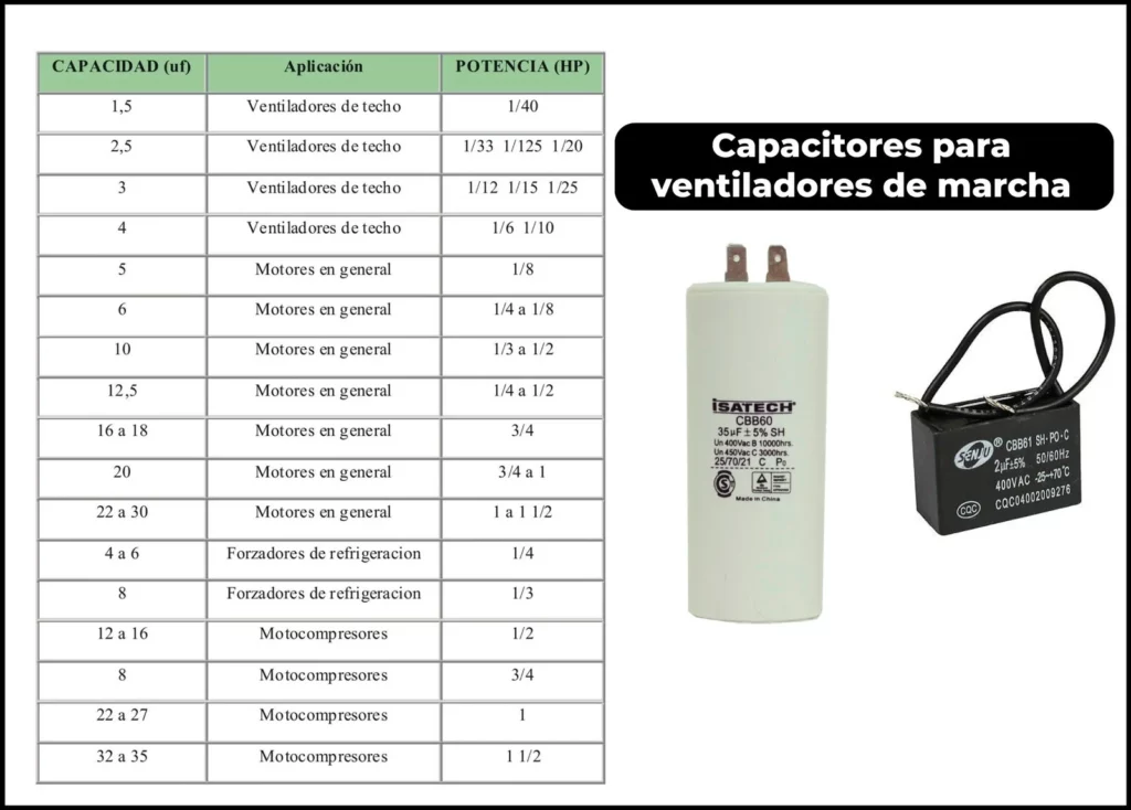
Table of starting capacitors for single-phase motors
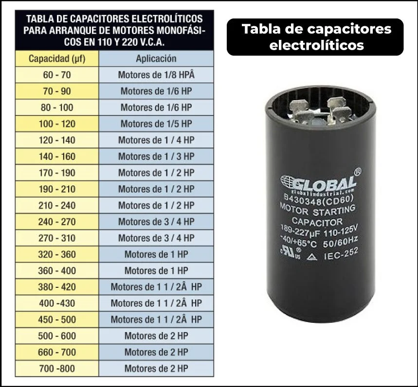
Table of Start and Run Capacitors for Single Phase Capacitors
In this table, which is very similar to the previous one, I attach capacitor values for single-phase motors.
both working and starting capacitors, this way you will have the most user-friendly information in a single image
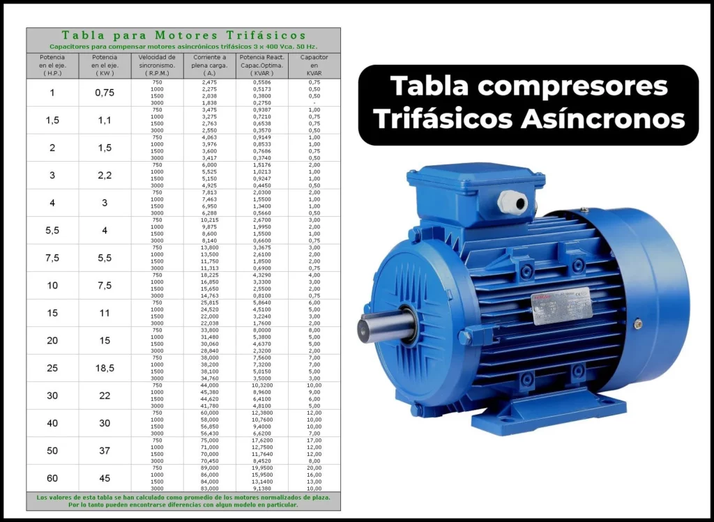
Capacitor Table for Three-Phase Electric Motors
As a general rule, low-power three-phase electric motors have an operating voltage of 220 VD / 380 VY, but we must always make sure .
To do this, it is best to look at the motor’s nameplate. Where the voltages and connection will be indicated to know the type of Capacitor they use.
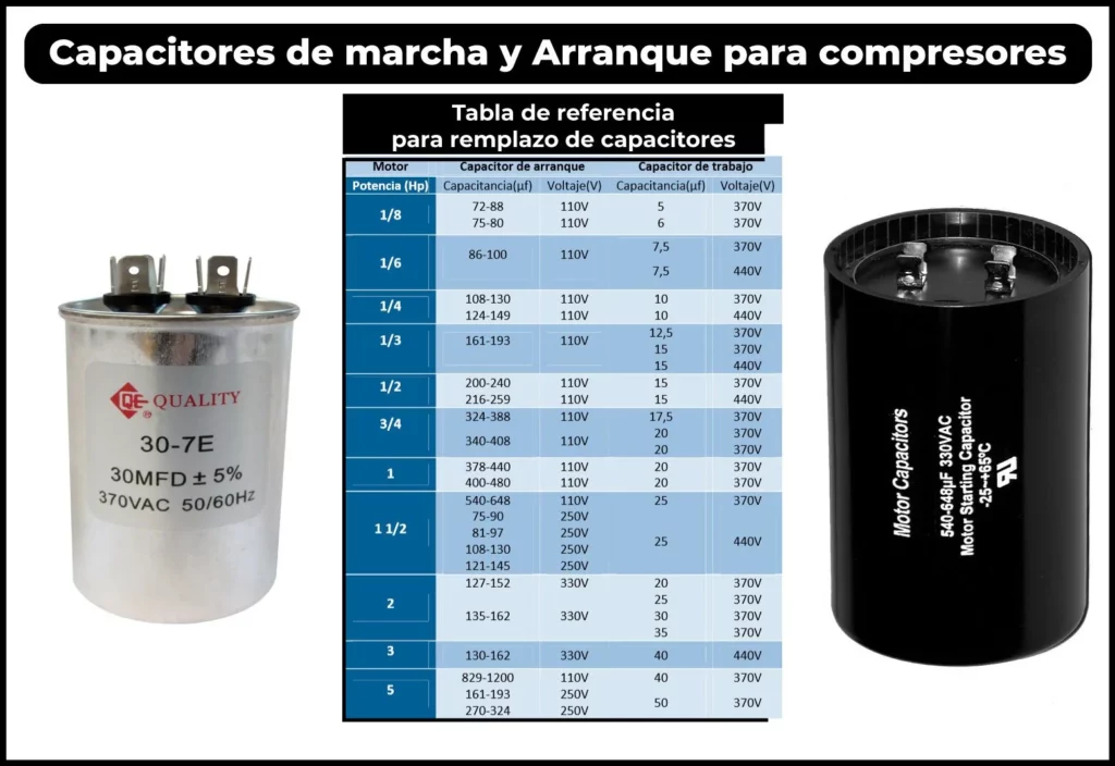
Fan run capacitor table
If you need to change a running or permanent fan capacitor, this table attached below can guide you to resolve the fault of the equipment you are repairing:
Understanding Starting Capacitors for Compressors: A Comprehensive Guide
Introduction Starting capacitors play a crucial role in the efficient operation of compressors, especially in single-phase motors. They help generate the necessary starting torque and ensure smooth operation. This guide provides a detailed overview of starting capacitors, their importance, and how to select the right one for your compressor. We’ll also explore key specifications and troubleshooting tips to ensure optimal performance.
1. What is a Starting Capacitor?
A starting capacitor is an electrical component used in single-phase motors to create a phase shift, which generates the torque needed to start the motor. Without a starting capacitor, single-phase motors would struggle to start due to insufficient torque.
2. Key Functions of Starting Capacitors
Generate Starting Torque: Provides the necessary torque to start the compressor motor.
Phase Shift Creation: Creates a 90-degree phase shift to simulate a second phase in single-phase motors.
Smooth Operation: Ensures the motor starts smoothly without excessive current draw.
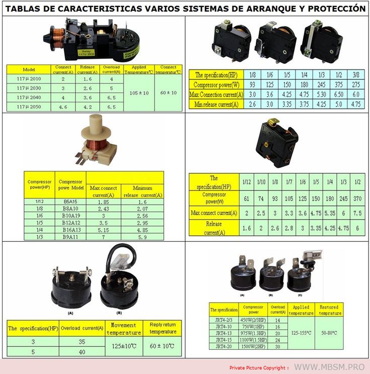
3. Table: Starting Capacitor Specifications for Compressors
Compressor Model
Power (W)
Voltage (V)
Capacitance (µF)
Max. Current (A)
Release Current (A)
BSA15
150
230
10
1.55
1.6
BSA10
250
230
15
2.43
2.07
B10A19
300
230
20
3.0
2.56
B12A12
350
230
25
3.5
2.95
B16A13
500
230
30
5.15
4.85
B9A11
750
230
35
7.0
5.9
4. How to Calculate the Right Capacitor for Your Compressor
The capacitance of a starting capacitor is critical for optimal performance. Here’s a simple formula to calculate the required capacitance:
Formula:
C=P×1062πfV2cos(ϕ)C=2πfV2cos(ϕ)P×106
Where:
CC = Capacitance (in microfarads, µF)
PP = Motor power (in watts, W)
ff = Frequency (in hertz, Hz, typically 50 or 60 Hz)
VV = Voltage (in volts, V)
cos(ϕ)cos(ϕ) = Power factor (typically 0.85 for motors)
Failed Capacitor: A faulty capacitor can prevent the motor from starting or cause it to overheat.
Incorrect Capacitance: Using a capacitor with the wrong capacitance can lead to insufficient torque or excessive current draw.
Overheating: Poor ventilation or excessive load can cause the capacitor to overheat and fail.
6. Troubleshooting Tips
Check Continuity: Use a multimeter to test the capacitor for continuity. A failed capacitor will show no continuity.
Measure Capacitance: Use a capacitance meter to ensure the capacitor’s value matches the required specifications.
Inspect for Physical Damage: Look for bulging, leaks, or burn marks on the capacitor, which indicate failure.
Test Under Load: Ensure the compressor starts smoothly and does not draw excessive current during startup.
7. Advantages of Using the Right Starting Capacitor
Improved Motor Lifespan: Reduces stress on the motor during startup.
Energy Efficiency: Minimizes power consumption during operation.
Reliable Performance: Ensures consistent and reliable compressor operation.
8. Conclusion
Selecting the right starting capacitor for your compressor is essential for ensuring efficient and reliable operation. By understanding the specifications, calculating the correct capacitance, and performing regular maintenance, you can extend the lifespan of your compressor and avoid costly repairs.
Mbsm.pro, Understanding, Motor, Starting , Systems, for, Compressor
Category: Chaud&Froid
written by www.mbsm.pro | 18 January 2025
Introduction Motor starting systems are critical in ensuring the efficient and safe operation of electric motors across various industries. Choosing the right starting method can significantly impact performance, energy consumption, and equipment longevity. In this post, we’ll explore the most common motor starting systems, their characteristics, advantages, and disadvantages to help you make informed decisions for your applications.
1. Direct-On-Line (DOL) Starting
Characteristics:
Starting current: 5 to 8 times the rated current.
Starting torque: 0.5 to 1.5 times the rated torque.
Direct connection of the stator to the power supply.
Advantages:
Simple and cost-effective.
No additional devices required.
Disadvantages:
High starting current may cause voltage drops in the network.
Not recommended for high-power motors.
2. Star-Delta Starting
Characteristics:
Starting current: 1.5 to 2.6 times the rated current.
Reduced voltage in star mode (3 times lower).
Requires a motor with compatible windings.
Advantages:
Reduces starting current.
Suitable for machines with low resistive torque or no-load starting.
Disadvantages:
Requires a specific motor type.
Not effective for heavy loads.
3. Part-Winding Starting
Characteristics:
Starting current: Approximately half of DOL starting.
Starting torque: Higher than star-delta.
Uses two parallel windings.
Advantages:
Lower starting current.
Higher starting torque compared to star-delta.
Disadvantages:
Rarely used in Europe.
Requires a motor with specific windings.
4. Stator Resistance Starting
Characteristics:
Starting current: 4.5 times the rated current.
Starting torque: 0.75 times the rated torque.
Resistors in series with the windings.
Advantages:
Reduces starting current.
No winding modification required.
Disadvantages:
Energy losses in resistors.
Requires a timer to remove resistors.
5. Autotransformer Starting
Characteristics:
Reduced voltage during starting.
Three stages: star, partial coupling, and full voltage.
Selectable transformation ratio.
Advantages:
Reduces starting current.
Flexible voltage selection.
Disadvantages:
Expensive and complex.
Requires additional space for the autotransformer.
6. Electronic Soft Starter
Characteristics:
Limits current and adjusts torque.
Smooth start and stop.
Electronic control of applied voltage.
Advantages:
Smooth starting reduces mechanical stress.
Energy savings.
Disadvantages:
Higher initial cost.
Requires maintenance of the electronic system.
7. Variable Frequency Drive (VFD) Starting
Characteristics:
Speed and torque control.
Suitable for high-inertia loads.
Optimizes energy consumption.
Advantages:
Precise speed control.
Ideal for applications requiring variable speed.
Disadvantages:
High initial cost.
Requires technical expertise for setup and maintenance.
Conclusion
Selecting the right motor starting system depends on factors such as motor size, load type, and operational requirements. While DOL starting is simple and cost-effective, more advanced systems like soft starters and VFDs offer greater control and efficiency, albeit at a higher cost. Understanding these systems will help you optimize performance, reduce energy consumption, and extend the lifespan of your equipment.
If you have any questions or need further assistance in choosing the right motor starting system for your application, feel free to leave a comment or contact us!
Tags: Motor Starting Systems, Electric Motors, Soft Starters, VFD, Star-Delta Starting, Industrial Automation Categories: Electrical Engineering, Industrial Automation, Energy Efficiency
table organizes the information for better readability and understanding:
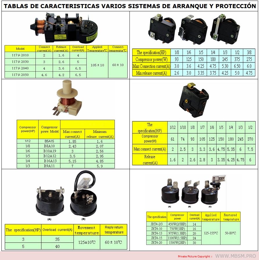
Content Table: Motor Starting Systems and Protection Specifications
1. General Specifications
Model
Concesor Current (A)
Relaxo Current (A)
Overload Current (A)
Applied Temperature (°C)
Concesor Temperature (°C)
1171/2010
2
1.6
4
–
–
1171/2030
3
2.6
5
105 ± 10
60 ± 10
1171/2040
4
3.6
6.5
–
–
1171/2050
4.6
4.2
6.5
–
–
2. Compressor Power Specifications (HF)
Component Power (HF)
Compressor Power Model
Max. Connection Current (A)
Minimum Release Current (A)
1/12
BSA15
1.55
1.6
1/8
BSA10
2.43
2.07
1/6
B10A19
3
2.56
1/5
B12A12
3.5
2.95
1/4
B16A13
5.15
4.85
1/3
B9A11
7
5.9
3. Compressor Power and Current Ratings
Component Power (HF)
Compressor Power (W)
Max. Connection Current (A)
Release Current (A)
1/12
61
2
1.6
1/10
74
2.5
2
1/8
93
3
2.6
1/7
105
3.3
2.8
1/6
125
3.6
3
1/5
150
4.75
3.35
1/4
180
5.35
4.25
1/3
245
6
4.75
1/2
370
7.5
6
4. IRFA Series Specifications
Model
Compressor Power (W)
Max. Connection Current (A)
Release Current (A)
IRFA-20
450W (20HF)
14
–
IRFA-10
750W (1HF)
16
–
IRFA-13
975W (1HF)
20
–
IRFA-15
1100W (2HF)
24
–
IRFA-20
1500W (2HF)
30
–
5. Additional Notes
Concesor Current: The current drawn by the compressor during operation.
Relaxo Current: The current at which the system releases or disconnects.
Overload Current: The maximum current the system can handle before tripping.
Applied Temperature: The operating temperature range for the system.
Concesor Temperature: The temperature range for the compressor during operation.
This table provides a clear and organized overview of the motor starting and protection systems, including their specifications and performance metrics. Let me know if you need further assistance!
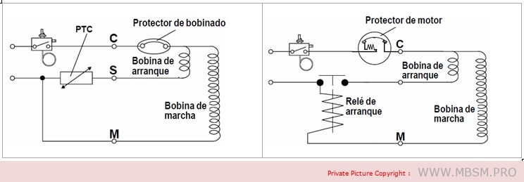
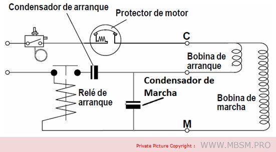
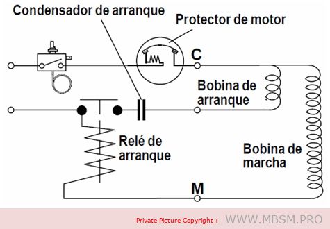
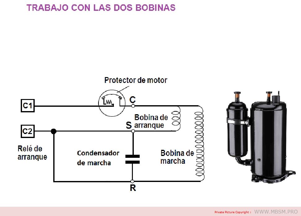
Sistemas de arranque:
En el caso del relé de arranque, cuando la energía es aplicada al compresor, la bobina solenoide del relé atrae la armadura del mismo para arriba produciendo el cierre de los contactos, energizando la bobina de arranque del motor. Cuando el motor del compresor alcanza la velocidad de funcionamiento, la corriente de la bobina principal del motor será tal que la bobina solenoide del relé desenergiza permitiendo que los contactos del relé se abran, desconectando de esta manera la bobina de arranque del motor.
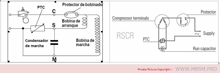
The PTC is a semiconductor with a positive temperature coefficient, which means that it offers no resistance to the passage of current when the unit is cold. When the unit is turned on, the current passing through the PTC causes it to heat up rapidly, creating such a high resistance in its circuit that the passage of current remains at a very low value but high enough to keep the PTC warm.
Prerequisites for using the PTC system:
– The thermostat must be used to ensure that the stop time allows for pressure equalisation in the system. – Depending on the size of the compressor, the stop period should be at least 3 to 5 minutes (e.g. the minimum times for TL are 3 minutes, and for SC 5 minutes).
The PTC system offers a number of advantages:
– Improved protection of the starter coil – PTC is not affected by voltage increases or decreases – Free from radio and television interference – No wear – Identical PTC starter system for many compressors of different sizes.
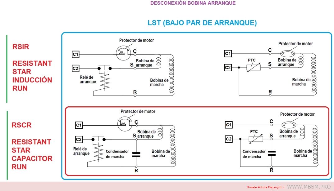
LST (low starting torque) engines
Compressors with RSIR and RSCR system motors have a low starting torque (LST) and are used in refrigeration appliances with capillary tubes, where pressure equalization takes place before each start.
The RSIR system incorporates a PTC thermistor or a relay and a bifilar winding (current relay) as starting equipment. The PTC needs to be kept off for a period of about 5 minutes to allow it to cool down before it can restart.
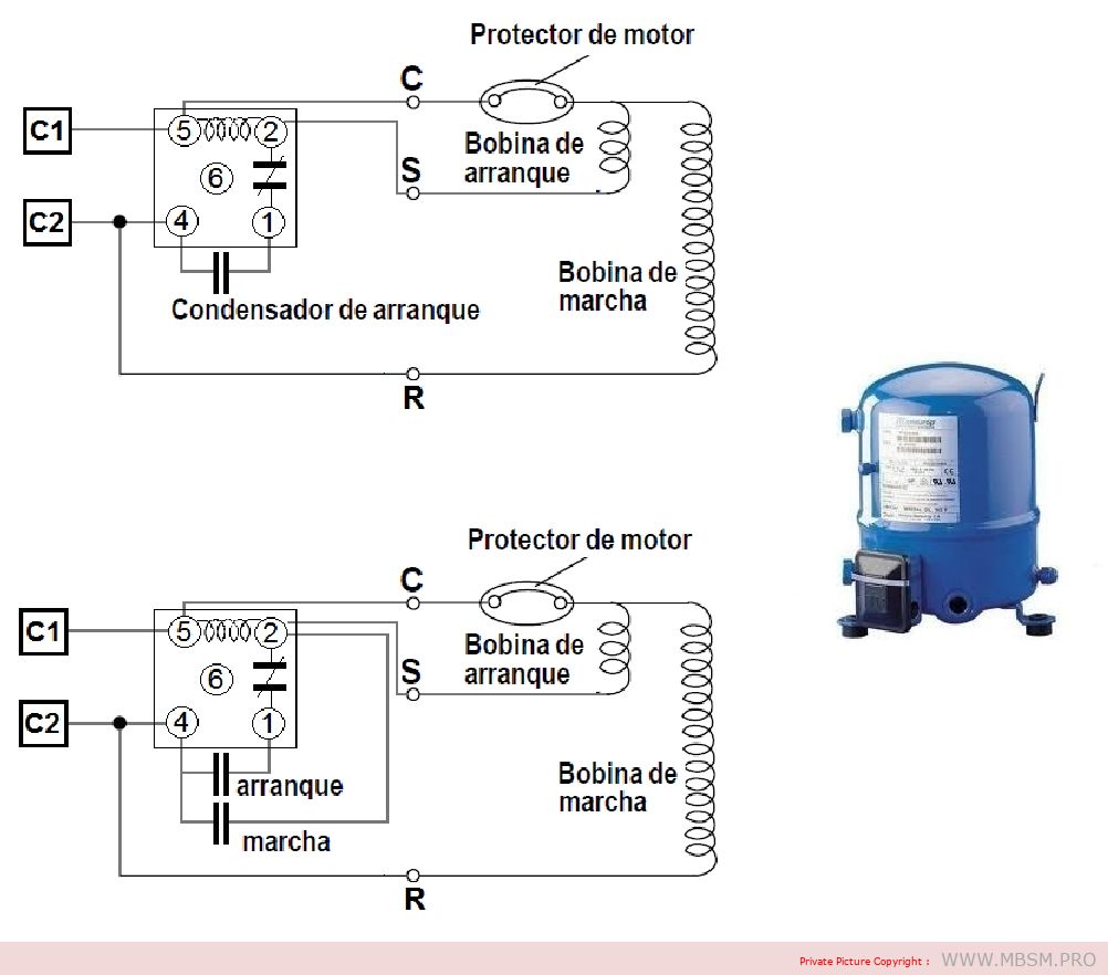
RSCR (Resistant Start Capacitor Run): Induction motor with resistor start and run capacitor.
The RSCR system, consisting of a PTC thermistor and a run capacitor, is mainly used in energy-optimized compressors.
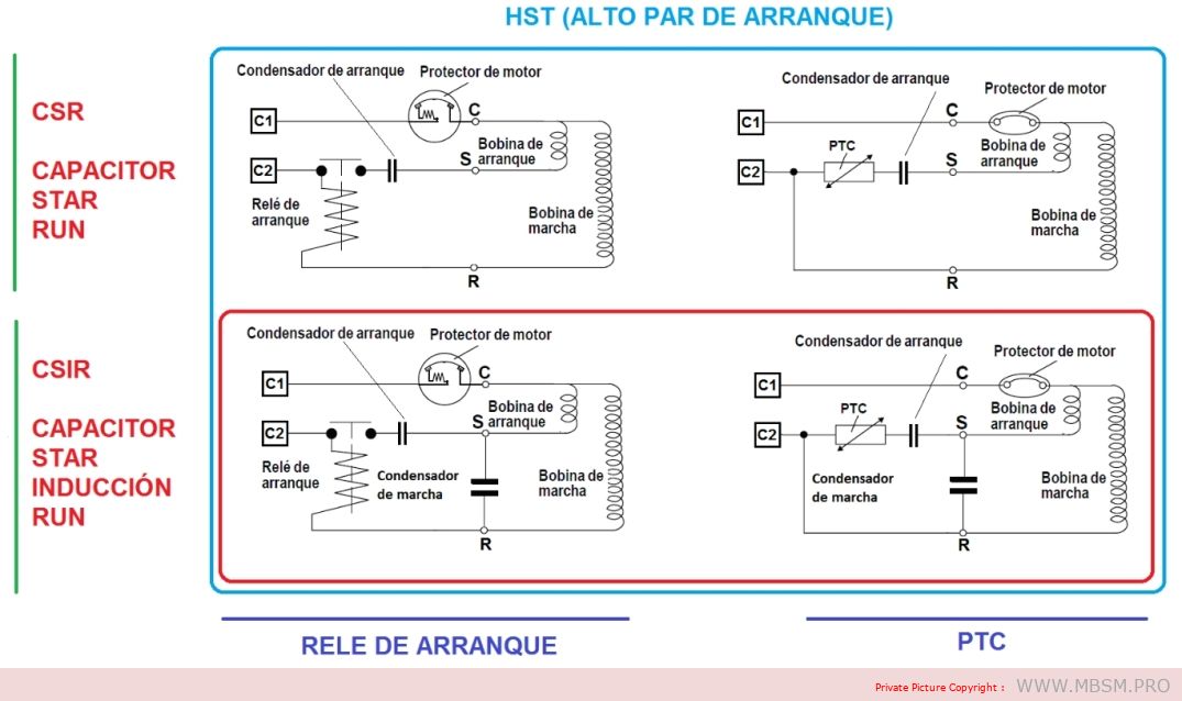
HST (High Starting Torque) Engines
Compressors with CSIR and CSR type motors have a high starting torque (HST) and can be used in refrigeration appliances with capillary tubes as well as in systems with expansion valve operation (without pressure equalization).
– CSR (Capacitor Start Run): Induction motor with start capacitor and run capacitor
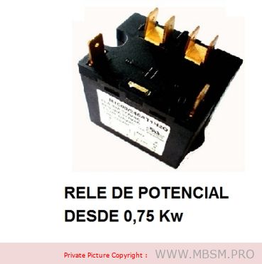
CRS systems require a voltage relay, a start capacitor and a run capacitor.
– CSIR (Capacitor Start Induction Run): Induction motor with starting capacitor.
The CSIR system consists of the starting relay and starting capacitor specified for each particular compressor type.
Graphic summary:
Conditions for a long service life
To achieve trouble-free operation and long service life of the hermetic compressor, the following conditions must be met:
1. The starting torque must be sufficient to enable the motor to start under the prevailing pressure conditions in the system. 2. The maximum torque of the motor must be sufficient to enable the motor to withstand the load conditions at start-up and during running. 3. During operation of the refrigeration system, the temperature of the compressor must never rise to levels that could damage its components. Condensation and compression temperatures must therefore be kept as low as possible. 4. Correct sizing of the refrigeration system in question, and a correct assessment of the operating conditions of the compressor under maximum loads. 5. Sufficient cleanliness and minimum residual moisture in the system.
Engine overload
The motor start-up is determined by the starting torque and/or the maximum torque of the motor. If the starting torque or the maximum torque are insufficient, the compressor cannot start or the start-up will be hindered and delayed due to the activation of the internal motor protector.
Repeated starting attempts subject the motor to overload, which will sooner or later result in failure. It is all a matter of selecting the right compressor for extreme working conditions.
Thermal overload
To ensure a long compressor life, operating conditions that lead to thermal decomposition of the materials used in the compressor must be avoided. The materials involved are coolant, oil and materials for motor insulation. Motor insulation consists of enamel for the copper winding, insulation for the stator core slot, insulating tape and power cables.
The R 134a, R 404A or R 507 refrigerants used today require advanced oils. Only special quality POE oils (polyester) are used.
For the application of compressors in domestic and commercial refrigeration devices with the refrigerants that are currently available, it is advisable to comply with the following rules.
Coil temperature
The coil temperature must never exceed 125°C during continuous operation. For limited periods of time, e.g. during compressor start-up or in case of short load peaks, the temperature should not exceed 135°C.
For commercial refrigeration with R 134a, the same values apply as for domestic refrigeration. However, cooling the compressor by means of a fan is recommended.
Condensation temperature
When using R 600a or R 134a refrigerants, the condensation temperature during continuous operation must not exceed 60°C. During short load peaks, the temperature must not exceed 70°C.
In commercial refrigeration where R 404A and R 507 refrigerants are used, the condensation temperature limit is 48°C during continuous operation and 58°C during peak loads.
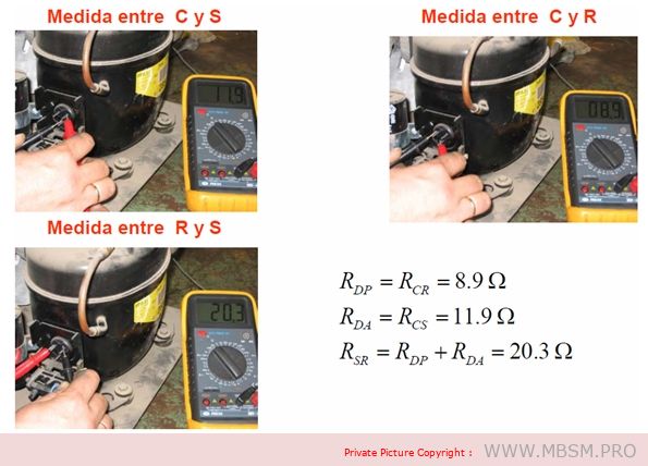
Checking the compressor coils.
We must take into account that we are going to check an electromechanical part since it has an electrical part that makes another mechanical part work and it is necessary to carry out several types of tests to be able to determine if it is damaged and if it is possible to find out which part of the compressor is damaged. For these tests we will need measuring tools and a little expertise since in some we will use the senses, we will divide the tests into two parts, one when it is installed and the other when the compressor is alone without being installed.
Measure continuity between the compressor coils:
For this test we will need a tester that measures continuity, we will have to disconnect the compressor cables, the test consists of verifying that there is continuity between the compressor terminals and measuring two by two we verify if there is no continuity in these terminals, we must take into account the temperature of the compressor, if it is cold the coil is open (damaged), if the compressor is hot we must wait for it to cool down because it may be that the thermal switch is open due to high temperature and we perform the test again.
If you are disconnected or off the computer, this test is performed in the same way.
Test if the amperage is too high:
For this test we will need a clamp meter and we will place it in one of the compressor lines, either the common one, preferably the start (maintenance) line, it should not be placed on the start-up line because it will not give us the measurement we need to check, we must know the normal working amperage of the compressor, start it, wait for it to stabilize, at start-up it normally consumes 5 times the working amperage, we wait for it to stabilize and if it is above that indicated on the plate it is too high in amperage, in this case we will have to check, capacitor, ventilation, pressures, voltage tension, to determine if it is because of the compressor or an external cause. If the compressor is disconnected from the equipment and the amperage exceeds that indicated it is a sign that it is damaged and we should not install it.
Determine if compressor pumps well:
Pressure test: it is not advisable to measure the output pressure, however there are technicians who when buying a used compressor usually measure the high pressure, if it exceeds 300 psi the compressor is fine and if when turning it off the pressure is maintained without it returning, it is an excellent sign that everything is fine, it is not low on compression since the valves do not return pressure, this test is not performed on rotary compressors because they work with the pressure and temperature of the same compressor to reach the normal working refrigerant gas pressure.
If the compressor is installed when measuring with the pressure gauge and registering that the high pressure does not rise and the low pressure is very high, it is a sign of decompression. If it is a rotary equipment, we look at the suction filter that is located at the compressor inlet to see if it freezes. If it is frozen it is due to obstruction. If, upon observing this, everything is normal, it is most likely that the pressures are destabilized due to low compression. Another sign is that the amperage with the low pressure high and the high pressure low will show a consumption well below normal since it is not exerting force to maintain a high pressure in the condenser.
Determine if the compressor is seized:
For this we need to use the ammeter or clamp meter when trying to start the having a suitable capacitor and in good condition it should not exceed the starting amperage which is 5 times the nominal or working amperage, if it exceeds it is a sign that it is blocked, we can use an additional starting aid to the capacitor and if with this the result is the same (taking into account that the voltage is normal) we will determine that the compressor is seized and it is necessary to replace it.
When I mention at the beginning that we should use our senses, I mean that if we are testing a compressor and we notice a strange noise when starting it, this is not a good sign, and if it is already in full operation and sounds unusual, it is a bad sign, as well as looking at the part where the cables are connected to the compressor, since this is a seal that sometimes gets damaged and allows oil to leak, be attentive and verify that the filter that is fixed by a belt in the case of rotary compressors is not subject to this belt being damaged, since it also produces noise, refrigerant gas leaks and vibrations, these are details that we should be very attentive to.
Note: We should always try to exhaust every last resource to determine if a compressor is damaged, because if we are technicians and they seek a second opinion, and it works in the hands of the second opinion, the client will think the worst of us and our reputation will be in jeopardy, and if the compressor is our property, we should also exhaust all resources, since it is the most expensive part of our air conditioning, both its individual price and the expenses generated in labor and materials for its installation. We must be very clear that it no longer works for ourselves and for others.
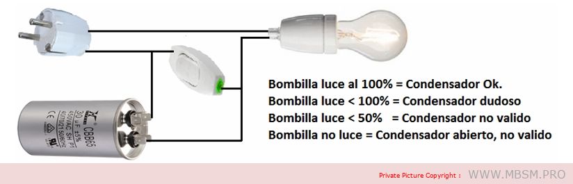
Checking the starting capacitor.
To test a starting capacitor in a simple way, we simply connect it in series with an incandescent light bulb and supply it with AC voltage. We will also complement the assembly with a normally open push button like the one used in doorbells, which we will connect in parallel with the capacitor according to the following diagram.
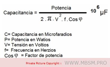
Calculation of the starting capacitor capacity:
Many refrigeration compressors are single-phase motors. The problem with supplying a motor with 230 V, with a single phase, means that the torque needed for starting is not generated. To “trick” the motor and generate a fictitious phase, a capacitor is used that shifts the supply voltage by 90º. In this way, we will have the necessary starting torque. To obtain the best and most powerful starting torque of the single-phase motor, which will result in the refrigeration compressor working better and with more force and not jamming… the capacity of the capacitor that obtains this 90º phase shift must be calculated.
It is not true that the larger the capacitor, the greater the starting torque of the single-phase motor. The only thing that is obtained is a greater phase shift, which will produce a lower starting torque of the single-phase motor. In fact, if the capacitor is too large, it may happen that the phase shift is 360º, that is, 0º, so that the single-phase motor would have no starting torque. In any case, capacitors with a higher or lower capacity than necessary will generate phase shifts lower or higher than the optimum, which will result in starting torque values lower than the optimum. Starting with starting torque lower than the optimum can result in our single-phase motor burning out; it has to make more effort than necessary to start, the intensity increases and the motor burns out, which would end up being damaged.
The highest starting torque for the single-phase motor is obtained when the phase shift we obtain with our capacitor is 90º. To obtain this phase shift we will proceed to calculate the capacitor of a single-phase motor in the following way.
Suppose we have an engine with the following characteristics
Power 150 W Working voltage 230 V. Frequency 50 Hz. Cosine of phi = 0.85
Applying the formula, the capacitance is 10.61 microfarads.
Therefore, the optimal ideal capacitor for the single-phase motor in the example is 10.61 uF, as 10.61 micro Farads is a capacitor value that we cannot find on the market, we will choose to buy the value that is closest in this case 10 micro Farads.
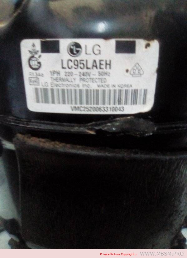
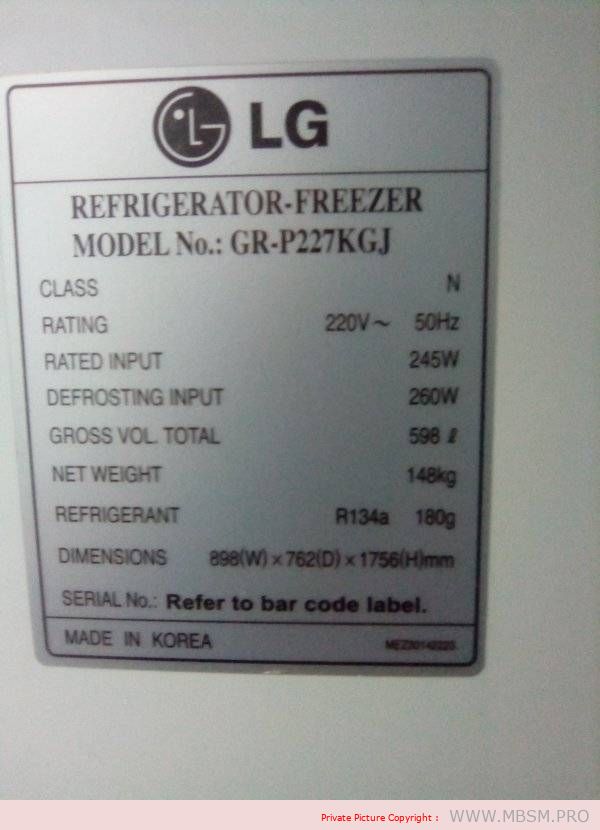
Refrigerant Type: R134a (a common refrigerant used in cooling systems)
Application: Refrigerator/Freezer
Volume/Capacity: 598 liters (L)
Weight: 180 grams (g)
Type: LBP (Low Back Pressure, typically used for refrigeration applications)
This compressor is likely designed for use in a refrigerator or freezer unit, with a cooling capacity suitable for a 598-liter appliance. The refrigerant used is R134a, which is common in domestic refrigeration systems. If you’re looking for a replacement part or technical specifications, ensure the model numbers (LC95LAEH, GR-P227KGJ) match your appliance.
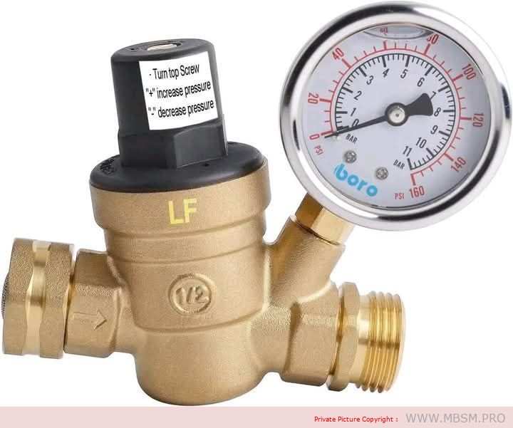
A water pressure regulator is a device used in water systems to reduce and adjust the pressure of water coming from the source (such as a public water supply) to a safe and constant level suitable for domestic or industrial use.
Importance of a Water Pressure Regulator:
Protecting Pipes and Appliances:
Prevents damage caused by high water pressure that may affect plumbing systems and appliances such as washing machines and water heaters.
Reducing Water Consumption:
Reduces excessive water flow, helping to conserve water and lower bills.
Improving Performance:
Ensures a consistent water flow, enhancing the efficiency of appliances and providing a better user experience.
Extending System Lifespan:
Prevents excessive pressure that may cause leaks or damage to pipes and fittings.
Components of a Water Pressure Regulator:
Pressure-Reducing Valve:
The part responsible for reducing water pressure to the desired level.
Internal Spring:
Controls the pressure and ensures it remains stable at the set value.
Pressure Gauge:
Displays the current pressure level (available in some models).
Inlet and Outlet:
Connections that link the regulator to the water source and the pipes leading to the point of use.
Types of Water Pressure Regulators:
Fixed Regulator:
Reduces pressure to a specific, non-adjustable level.
Adjustable Regulator:
Allows the user to adjust the pressure according to their needs.
Integrated Water Pressure Regulator:
Includes additional features such as a pressure gauge or an internal filter.
How to Choose the Right Water Pressure Regulator:
Water Pressure at the Source:
Determine the incoming water pressure to select a regulator that suits the current pressure.
Type of Use:
Choose a regulator suitable for domestic or industrial use.
Construction Materials:
Ensure the regulator is made of corrosion-resistant materials such as brass or stainless steel.
Pipe Size:
Make sure the connection size is compatible with your water pipes.
Advantages of Using a Water Pressure Regulator:
Reducing the Risk of Bursts:
Prevents pipe damage due to sudden high pressure.
Maintaining Stable Water Flow:
Provides consistent water pressure for appliances and daily use.
Saving on Bills:
Helps reduce water consumption, lowering costs.
Reducing Noise:
Minimizes noise caused by high-speed water flow in pipes.
Maintenance and Common Issues:
Clogged Filter:
Accumulation of sediment and debris can cause blockages. Clean the filter regularly.
Damaged Internal Spring:
The spring may lose its elasticity over time, affecting the regulator’s performance. Replace it if necessary.
Water Leaks:
Ensure connections are tightly sealed and replace damaged rubber seals.
Unstable Pressure:
This may be due to a damaged valve or spring. Inspect the regulator and replace faulty parts.
Maintenance Tips:
Regularly inspect the regulator to ensure it is functioning efficiently.
Clean the internal filter every 6 months or as needed.
Check for leaks in the connections.
Replace the regulator if it is significantly damaged or unable to maintain pressure.
Conclusion:
A water pressure regulator is an essential device for protecting water systems and household appliances from high pressure. By choosing the right type and performing regular maintenance, you can ensure a safe and consistent water flow while saving on costs and extending the lifespan of your systems.
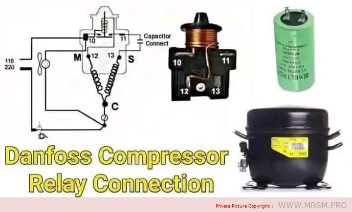
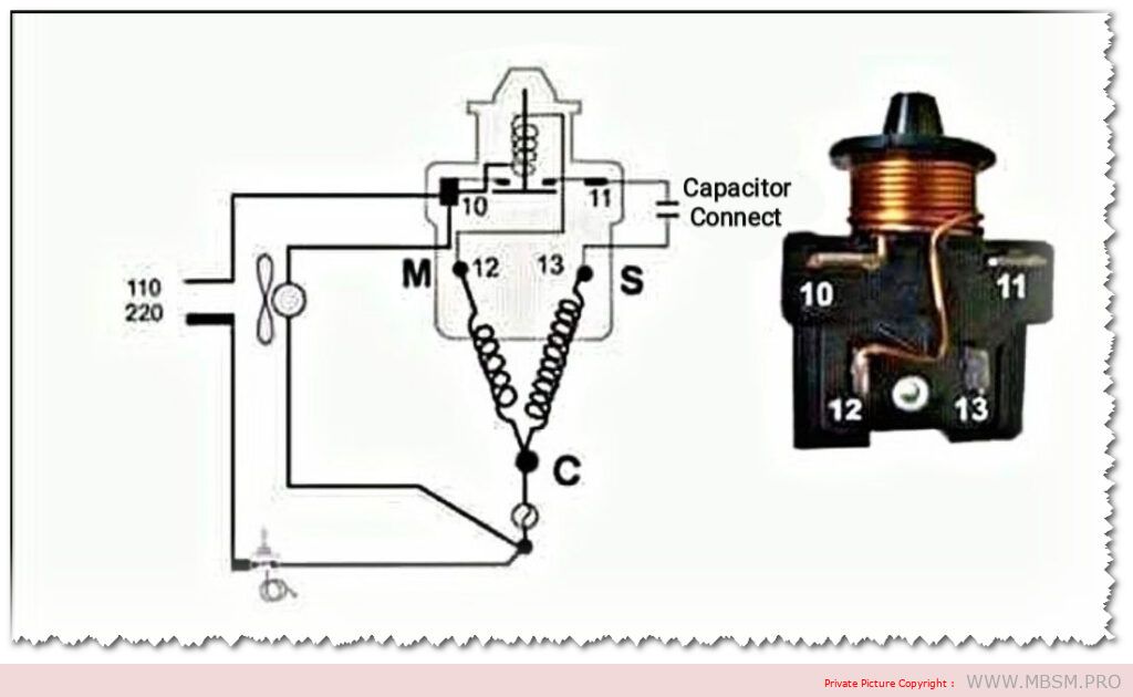
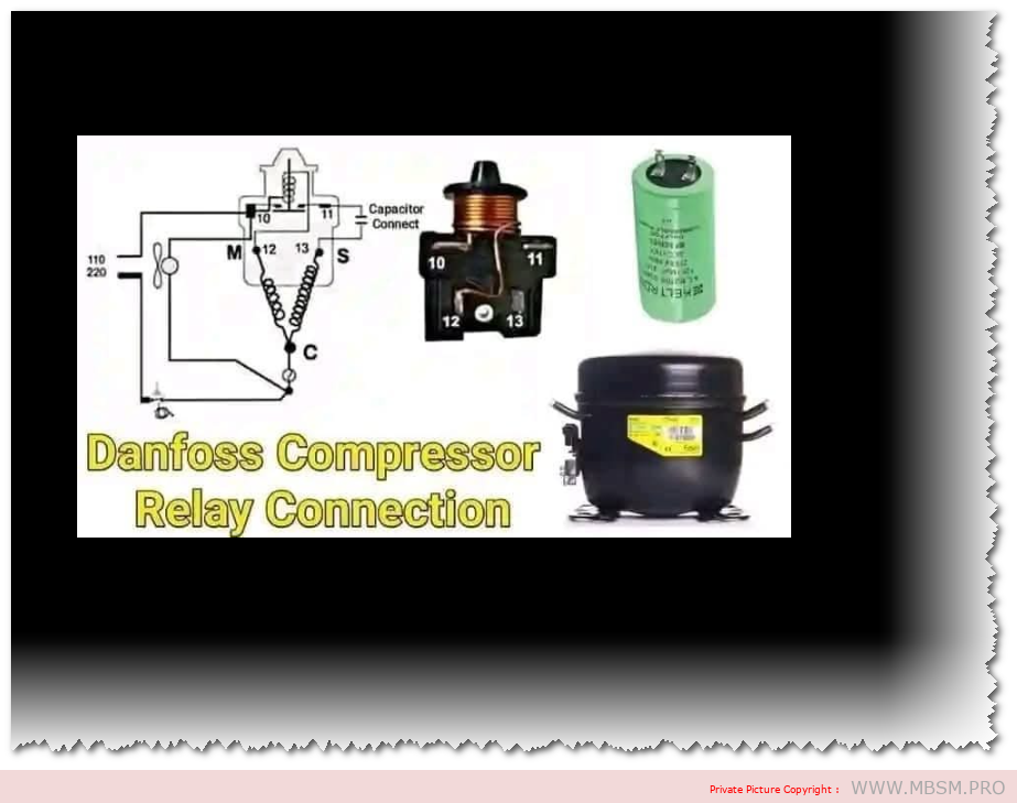
Danfoss Relay Connection Diagram for the Electric Compressor in Refrigeration Systems
Below is a detailed explanation of the components and connection diagram of the Danfoss relay for the electric compressor used in refrigeration systems:
1. Components of the Diagram
Compressor:
The compressor is the heart of the refrigeration system, responsible for compressing the refrigerant (freon) and circulating it through the system.
Relay:
The relay is used to provide additional electrical current to the start terminal (S) of the compressor, helping it start smoothly.
Capacitor:
The capacitor improves the compressor’s torque during startup, reducing the load on the electric motor.
Electrical Circuit Diagram:
The diagram shows how the compressor terminals (C, S, R) are connected to the relay, capacitor, and power source.
2. Compressor Terminal Connections
C (Common):
The common terminal connected to both the run and start windings.
R (Run):
The terminal responsible for continuous operation of the compressor after startup.
S (Start):
The terminal responsible for starting the compressor with the help of the relay and capacitor.
3. Steps to Connect the Relay to the Compressor
A. Connecting the Capacitor:
The capacitor is connected between the S (Start) terminal and the R (Run) terminal to support startup torque.
B. Connecting the Relay:
Terminals 10 and 11:
Connected to the power source and the run resistor.
Terminals 12 and 13:
Connected to the compressor terminals: S (Start) and C (Common).
C. Power Supply:
The circuit is powered by a 110V or 220V source (depending on the system used).
4. How the Relay Works
When power is connected, the relay sends additional current to the start terminal (S) via the capacitor.
Once the compressor starts running, the relay automatically cuts off the current to the start terminal.
The compressor continues to operate through the current flowing to the run terminal (R).
5. Importance of Correct Relay Connection
Compressor Protection:
Ensures safe compressor operation during startup.
Energy Saving:
The relay cuts off the startup current after operation to avoid overload.
Performance Improvement:
Helps stabilize compressor operation.
6. Verification Steps After Connection
A. Checking Terminal Connections (C, R, S):
Use a resistance meter (ohmmeter) to verify correct terminal connections.
B. Testing the Relay:
Ensure the relay sends startup current when powered.
C. Testing the Capacitor:
Measure the capacitor’s capacitance (microfarads) using a capacitor tester.
D. Running the Compressor:
Start the system and check for stable compressor operation.
Listen for noise: If it is loud, there may be a connection error.
7. Common Faults and Solutions
A. Compressor Fails to Start:
Cause: Faulty relay or capacitor.
Solution: Test the relay and capacitor and replace them if necessary.
B. Compressor Runs Briefly and Stops:
Cause: High current or excessive load.
Solution: Ensure the external capacitor is clean and there is proper airflow around the unit.
C. Incorrect Connection:
Cause: Swapped terminals (C, R, S).
Solution: Use a resistance meter to accurately identify the terminals.
8. Important Tip
Ensure:
Terminals are connected correctly according to the diagram.
Use a capacitor that matches the compressor’s specifications.
Test the relay before installation to ensure no internal damage.
Conclusion
Correctly connecting the Danfoss relay is crucial for ensuring safe and efficient compressor operation in refrigeration systems. Follow the diagram carefully and perform the necessary tests to avoid malfunctions and improve system performance.
Terms of Use Agreement
written by www.mbsm.pro | 18 January 2025
Effective Date: December 24, 2024
Welcome to MBSM.pro! By accessing or using our website, you agree to comply with and be bound by the following terms and conditions. Please read these Terms of Use carefully before using our site.
1. Acceptance of Terms
By accessing or using MBSM.pro, you acknowledge that you have read, understood, and agree to be bound by these Terms of Use and our Privacy Policy. If you do not agree with these terms, please do not use our website.
2. Changes to Terms
We reserve the right to modify these Terms of Use at any time. Any changes will be effective immediately upon posting on this page. Your continued use of the site after any changes indicates your acceptance of the new terms.
3. User Accounts
To access certain features of our site, you may be required to create an account. You agree to provide accurate, current, and complete information during the registration process and to update such information to keep it accurate, current, and complete. You are responsible for maintaining the confidentiality of your account credentials and for all activities that occur under your account.
4. User Conduct
You agree not to engage in any of the following prohibited activities:
Using the site for any unlawful purpose.
Attempting to gain unauthorized access to any portion of the site or any other systems or networks connected to the site.
Interfering with or disrupting the security, integrity, or performance of the site.
Transmitting any viruses, malware, or harmful code.
5. Intellectual Property Rights
All content on MBSM.pro, including text, graphics, logos, images, and software, is the property of MBSM.pro or its licensors and is protected by copyright, trademark, and other intellectual property laws. You may not reproduce, distribute, modify, or create derivative works from any content without our prior written consent.
6. Third-Party Links
Our website may contain links to third-party websites that are not owned or controlled by MBSM.pro. We have no control over and assume no responsibility for the content, privacy policies, or practices of any third-party sites. We encourage you to review the terms and conditions and privacy policies of any third-party sites you visit.
7. Limitation of Liability
To the fullest extent permitted by law, MBSM.pro shall not be liable for any direct, indirect, incidental, special, consequential, or punitive damages arising from your use of or inability to use the site. This includes but is not limited to damages for loss of profits, goodwill, use, data, or other intangible losses.
8. Indemnification
You agree to indemnify and hold harmless MBSM.pro and its affiliates from any claims, losses, liabilities, damages, costs, or expenses (including reasonable attorneys’ fees) arising out of or related to your use of the site or your violation of these Terms of Use.
9. Governing Law
These Terms of Use shall be governed by and construed in accordance with the laws of [Your Jurisdiction], without regard to its conflict of law principles.
10. Contact Us
If you have any questions about these Terms of Use or need further information about our services, please contact us at:Email: [mbsmgroup@gmail.com]
Privacy Policy
written by www.mbsm.pro | 18 January 2025
Effective Date: December 24, 2024
At MBSM.pro, we value your privacy and are committed to protecting your personal information. This Privacy Policy outlines how we collect, use, disclose, and safeguard your information when you visit our website.
1. Information We Collect
We may collect the following types of personal information:
Personal Identification Information: Name, email address, phone number, and any other information you provide when you fill out forms on our site.
Non-Personal Identification Information: Browser type, Internet Service Provider (ISP), referring/exit pages, and date/time stamps.
2. How We Use Your Information
We use the information we collect for various purposes, including:
To provide and maintain our website.
To notify you about changes to our services.
To allow you to participate in interactive features of our service when you choose to do so.
To provide customer support.
To gather analysis or valuable information so that we can improve our website.
To monitor the usage of our website.
To detect, prevent, and address technical issues.
3. Cookies and Tracking Technologies
Our website uses cookies and similar tracking technologies to enhance your experience. You can instruct your browser to refuse all cookies or to indicate when a cookie is being sent. However, if you do not accept cookies, you may not be able to use some portions of our site.
4. Data Sharing and Disclosure
We do not sell or rent your personal data to third parties. We may share your information in the following circumstances:
With service providers to monitor and analyze the use of our website.
To comply with legal obligations or protect and defend our rights.
5. Your Rights
Depending on your location, you may have certain rights regarding your personal data:
The right to access – You have the right to request copies of your personal data.
The right to rectification – You have the right to request that we correct any information you believe is inaccurate.
The right to erasure – You have the right to request that we erase your personal data under certain conditions.
6. Security of Your Information
The security of your personal information is important to us. We strive to implement and maintain reasonable, commercially acceptable security procedures and practices appropriate to the nature of the information we store to protect it from unauthorized access, destruction, use, modification, or disclosure.
7. Changes to This Privacy Policy
We may update our Privacy Policy from time to time. We will notify you of any changes by posting the new Privacy Policy on this page with an updated effective date.
8. Contact Us
If you have any questions about this Privacy Policy or our data practices, please contact us at:Email: [mbsmgroup@gmail.com]
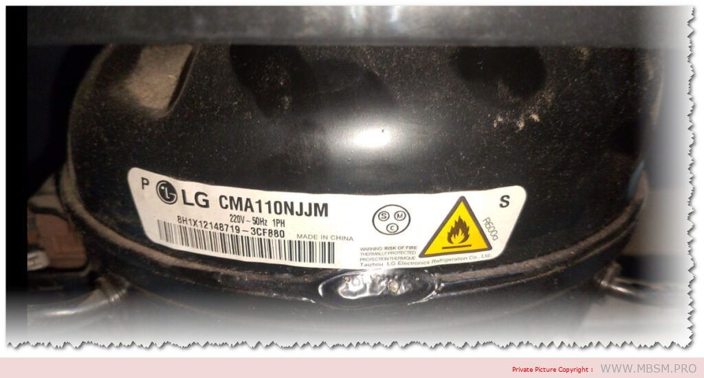
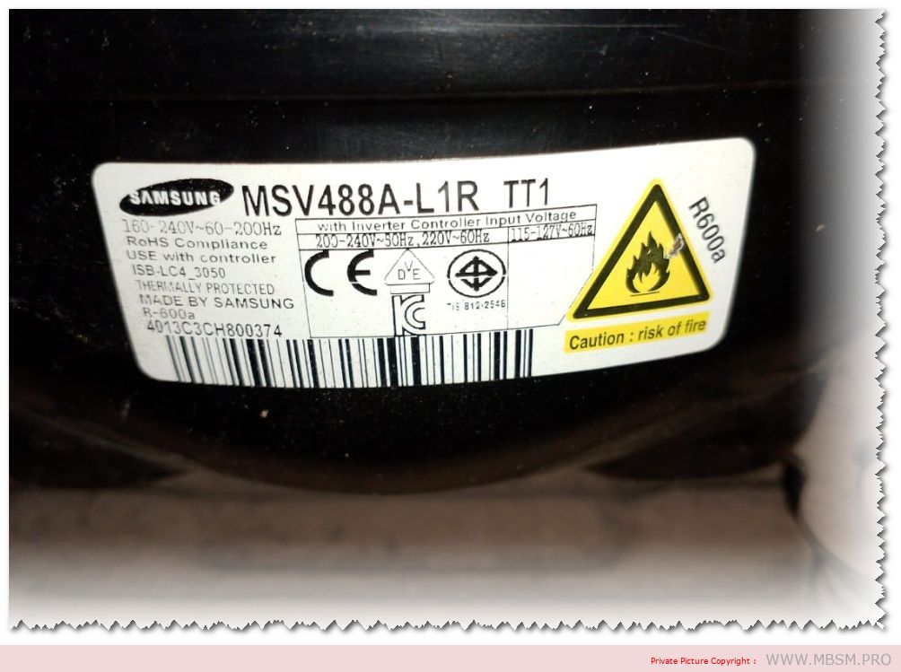
Mbsm.pro, Comparaison personnalisée des deux compresseurs, CMA110NJJM, MSV488A-L1R
Category: compressor
written by www.mbsm.pro | 18 January 2025
Comparaison personnalisée des deux compresseurs
1. Compresseur MBSM.PRO LG – CMA110NJJM
Marque/Modèle : MBSM.PRO, LG, CMA110NJJM
Type : Compresseur classique
Technologie : RCSB
Phase et Tension : 1 phase / 220V / 50Hz
Puissance : 170 kcal (676 BTH / 198 W)
Chevaux Vapeur (HP) : 1/4 CV
Réfrigérant : R600a
Application : LBP (Basse Pression de Vapeur)
Vitesse : Fixe
2. Compresseur Samsung Inverter – MSV488A-L1R
Marque/Modèle : Samsung, MSV488A-L1R
Type : Compresseur BLDC (moteur à courant continu sans balais)
Technologie : Onduleur (Inverter)
Phase et Tension : 115/220V
Cylindrée : 8,82 cm³
Chevaux Vapeur (HP) : 1/6 CV
Réfrigérant : R600a
Matériau : Acier
Avantages : Technologie Inverter pour une meilleure efficacité énergétique et régulation de la vitesse.
Comparaison Technique
Caractéristique
MBSM.PRO LG CMA110NJJM
Samsung MSV488A-L1R
Technologie
Classique (vitesse fixe)
Inverter (vitesse variable)
Type de Compresseur
RCSB
BLDC (sans balais)
Puissance
170 kcal / 198 W / 1/4 CV
1/6 CV
Réfrigérant
R600a
R600a
Phase et Tension
1 phase / 220V / 50Hz
115/220V
Application
LBP (Basse Pression de Vapeur)
Efficacité énergétique grâce à l’Inverter
Vitesse
Fixe
Variable
Matériau
Non spécifié
Acier
Analyse Comparée
Technologie Inverter vs Vitesse Fixe : Le compresseur Samsung MSV488A-L1R utilise la technologie Inverter, ce qui lui permet d’ajuster automatiquement sa vitesse pour optimiser la consommation énergétique, contrairement au LG CMA110NJJM, qui fonctionne à vitesse fixe.
Efficacité énergétique : Le compresseur Samsung est plus efficace en raison de la technologie BLDC et Inverter, offrant une meilleure gestion de la consommation d’énergie. Le compresseur LG, en revanche, est plus traditionnel avec une vitesse fixe.
Usage recommandé : Le modèle LG est plus adapté aux applications nécessitant une pression basse et une puissance fixe, tandis que le Samsung Inverter est recommandé pour ceux qui recherchent des économies d’énergie grâce à la régulation de la vitesse.
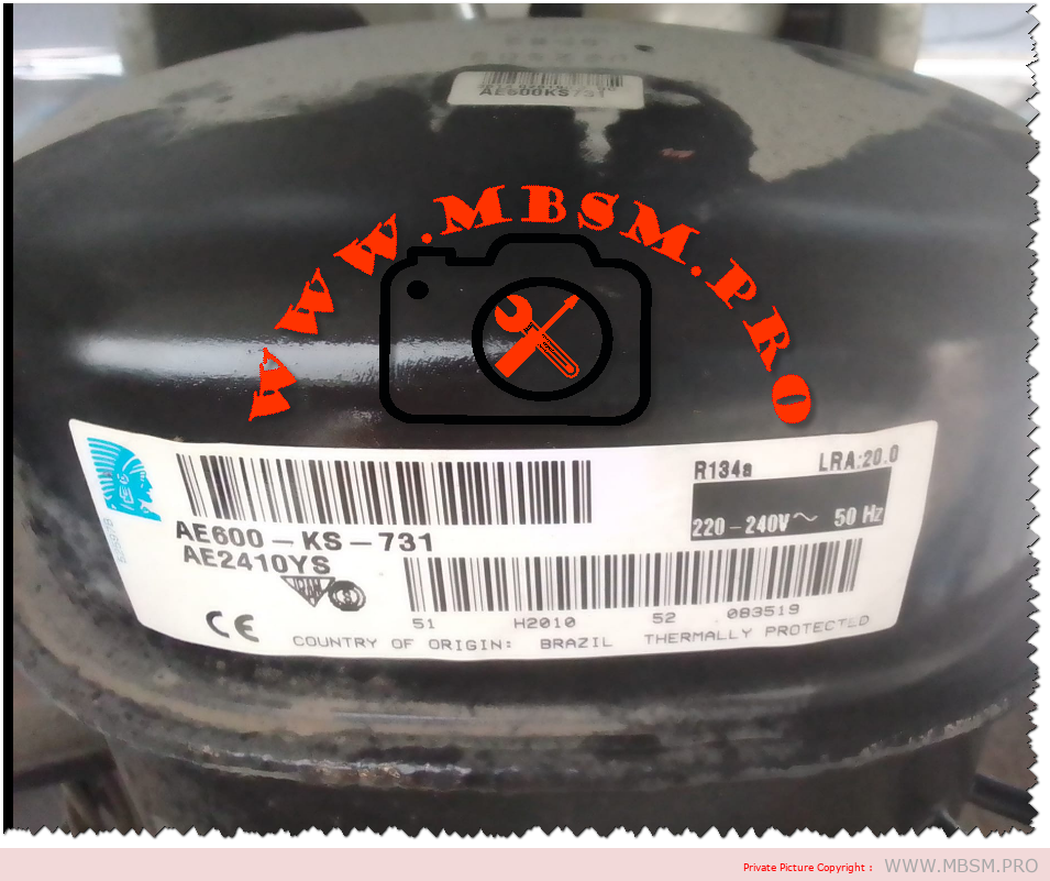
Tecumseh AE2410YS Compressor: Specifications and Applications
The Tecumseh AE2410YS is a versatile compressor designed for light commercial refrigeration applications. Known for its efficiency and reliability, this model is ideal for various cooling needs in commercial settings.
Key Specifications
Feature
Specification
Model
AE2410YS
Power
1/3 HP (approximately 250 W)
Refrigerant
R-134A
Voltage
220V
Type
Reciprocating Compressor
Weight
Approximately 45 lbs (20.4 kg)
Application Type
LBP (Low Back Pressure)
Cooling/Freezing
Primarily for Cooling Applications
Utilization
Commercial refrigeration, display cases, vending machines, and small walk-in coolers
Efficiency
Designed for effective cooling with reasonable energy consumption
Applications
The Tecumseh AE2410YS is primarily utilized in commercial refrigeration systems. Its low back pressure design makes it suitable for:
Display Cases: Keeping products at optimal temperatures while maintaining visibility.
Vending Machines: Ensuring beverages and snacks are kept cool and fresh.
Small Walk-in Coolers: Providing reliable cooling solutions for food storage in restaurants and convenience stores.
Conclusion
The Tecumseh AE2410YS compressor stands out in the market for its efficiency and adaptability in various cooling applications. Its design caters to the needs of commercial refrigeration, making it a preferred choice among professionals in the industry. For more information on this model or to explore other refrigeration solutions, visit our website or contact us directly. Feel free to make any adjustments or let me know if you need additional information included!
Danfoss offers a diverse range of compressors suitable for commercial refrigeration, including:
Scroll Compressors: Known for their efficiency and low noise levels, these compressors are ideal for applications like display cabinets and cold rooms.
Reciprocating Compressors: These are designed for both low and high-temperature applications, providing versatility in commercial settings.
Screw Compressors: Primarily used in industrial refrigeration systems, these compressors offer high efficiency and a broad capacity range.
Danfoss compressors are compatible with various refrigerants, including traditional options like R404A and R134A, as well as more environmentally friendly alternatives such as R290 (propane) and R1234yf. These innovations help meet stringent energy regulations globally