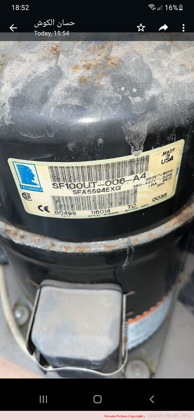
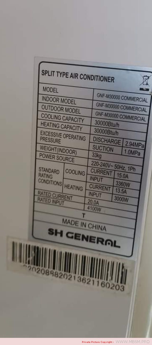
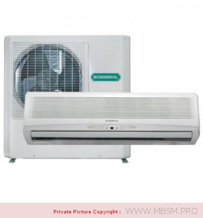
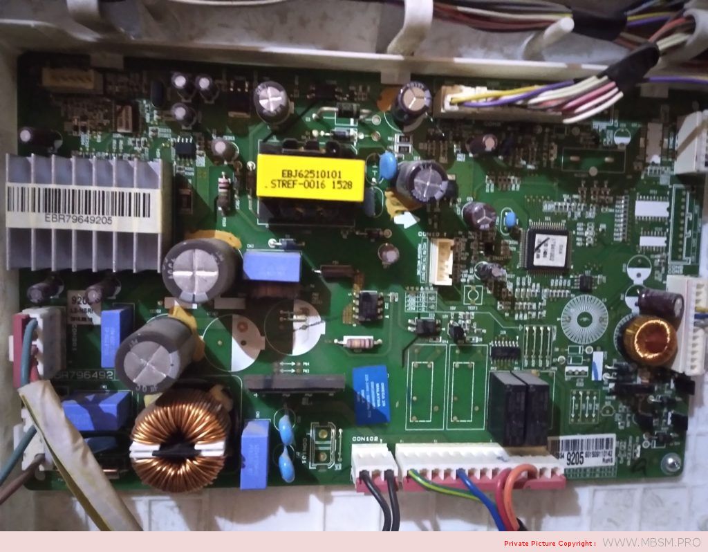
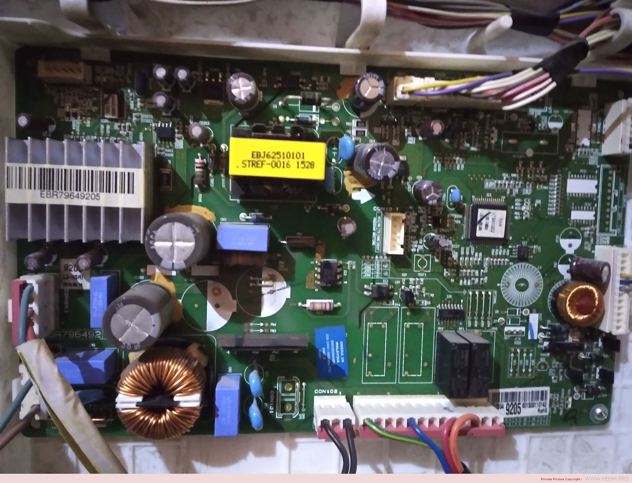
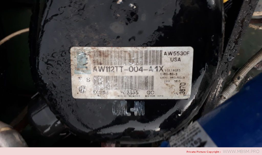
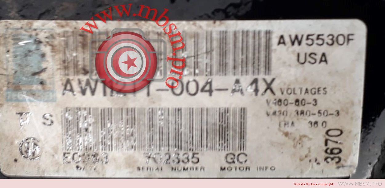
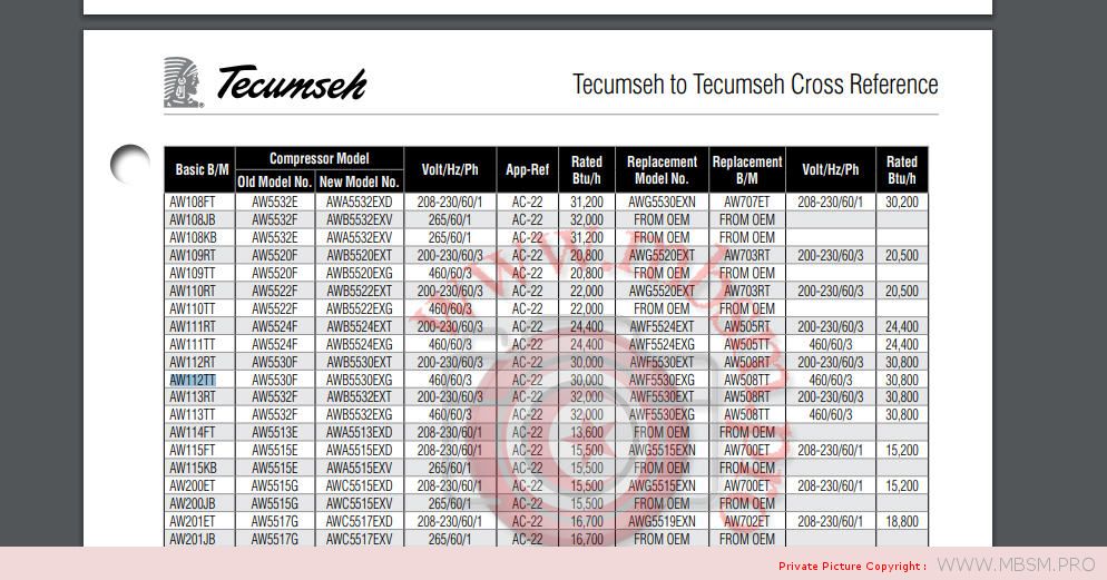
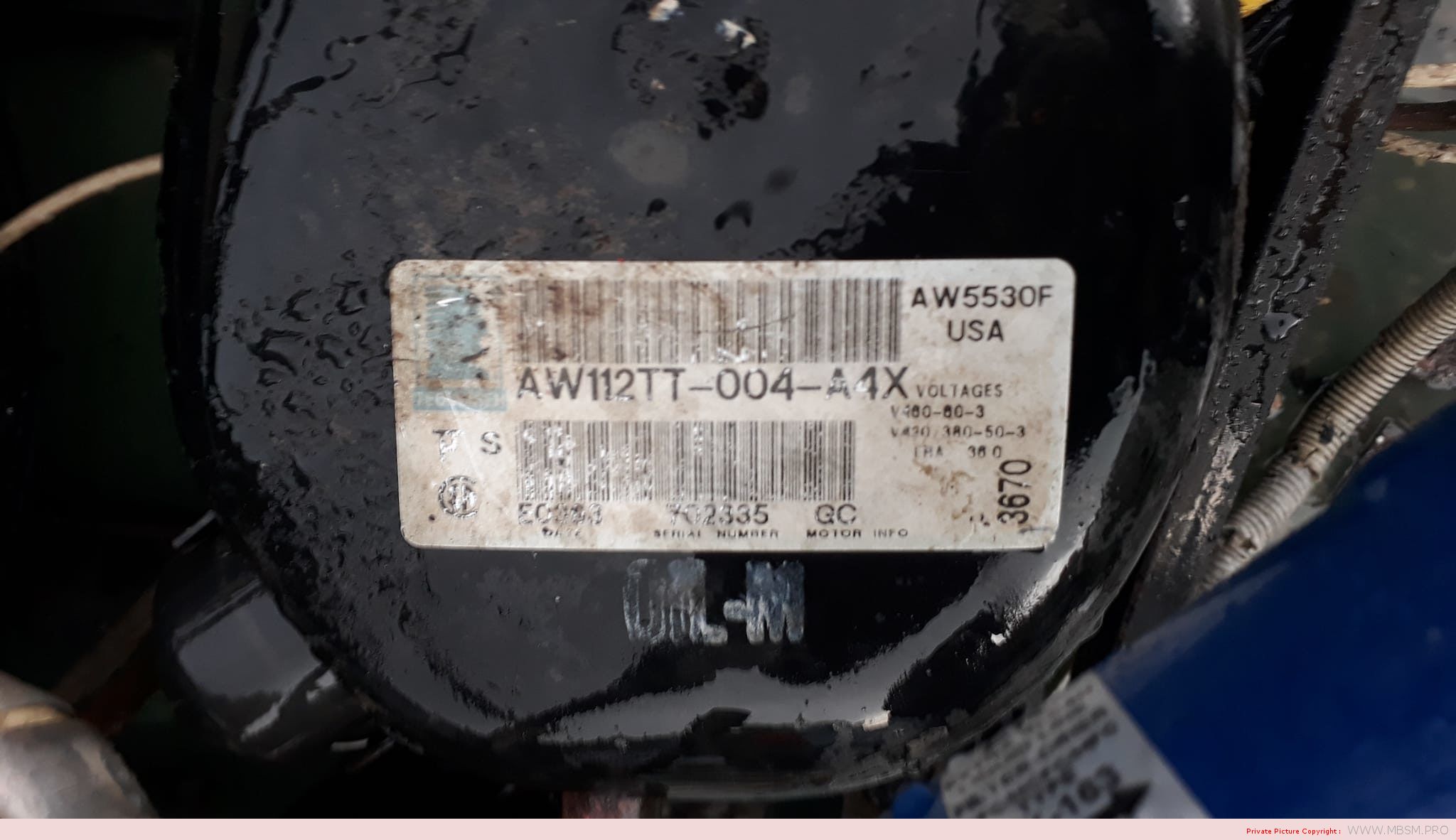
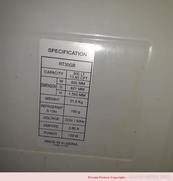
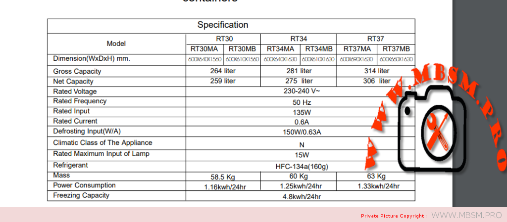
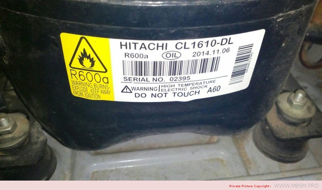
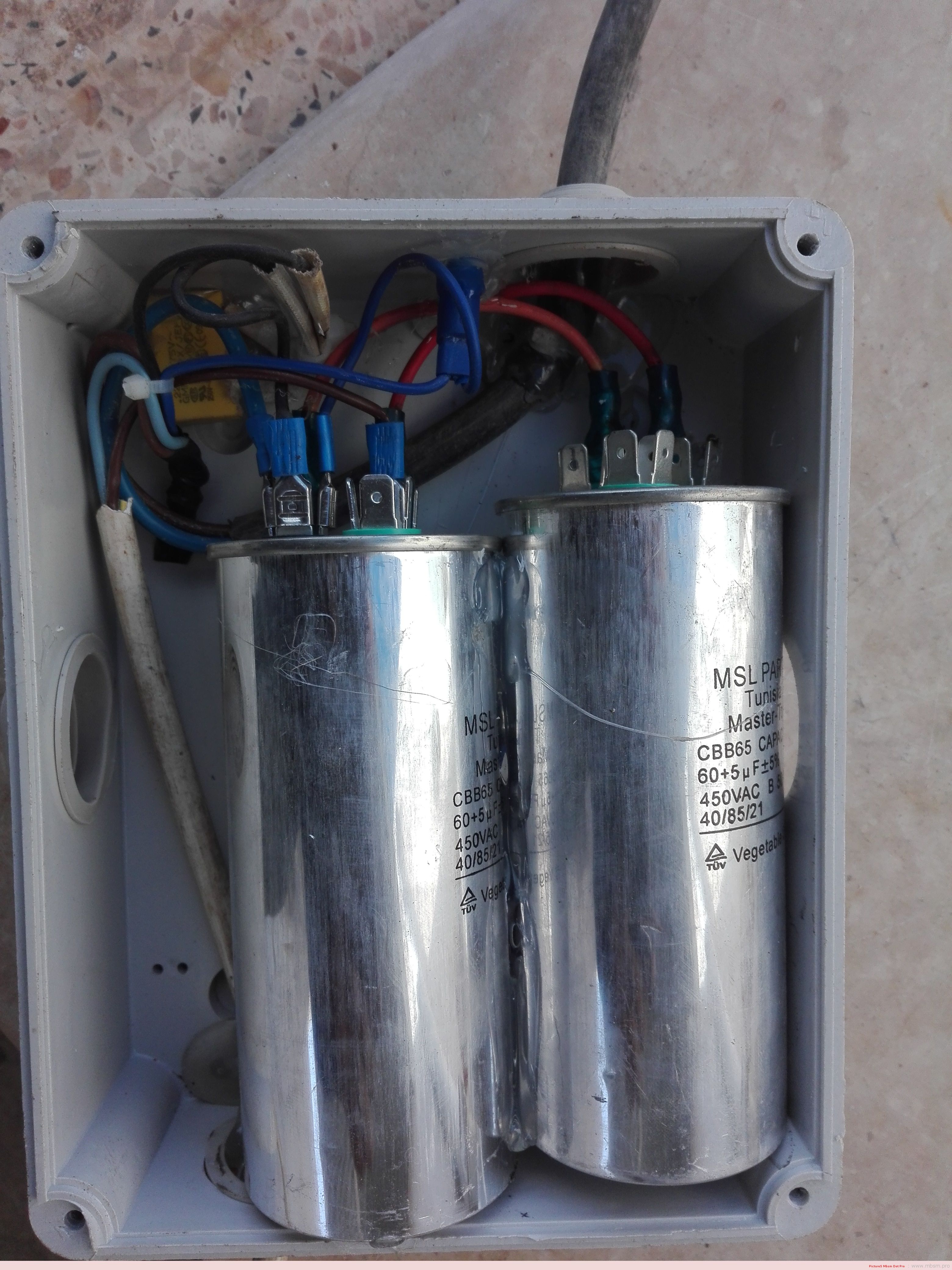
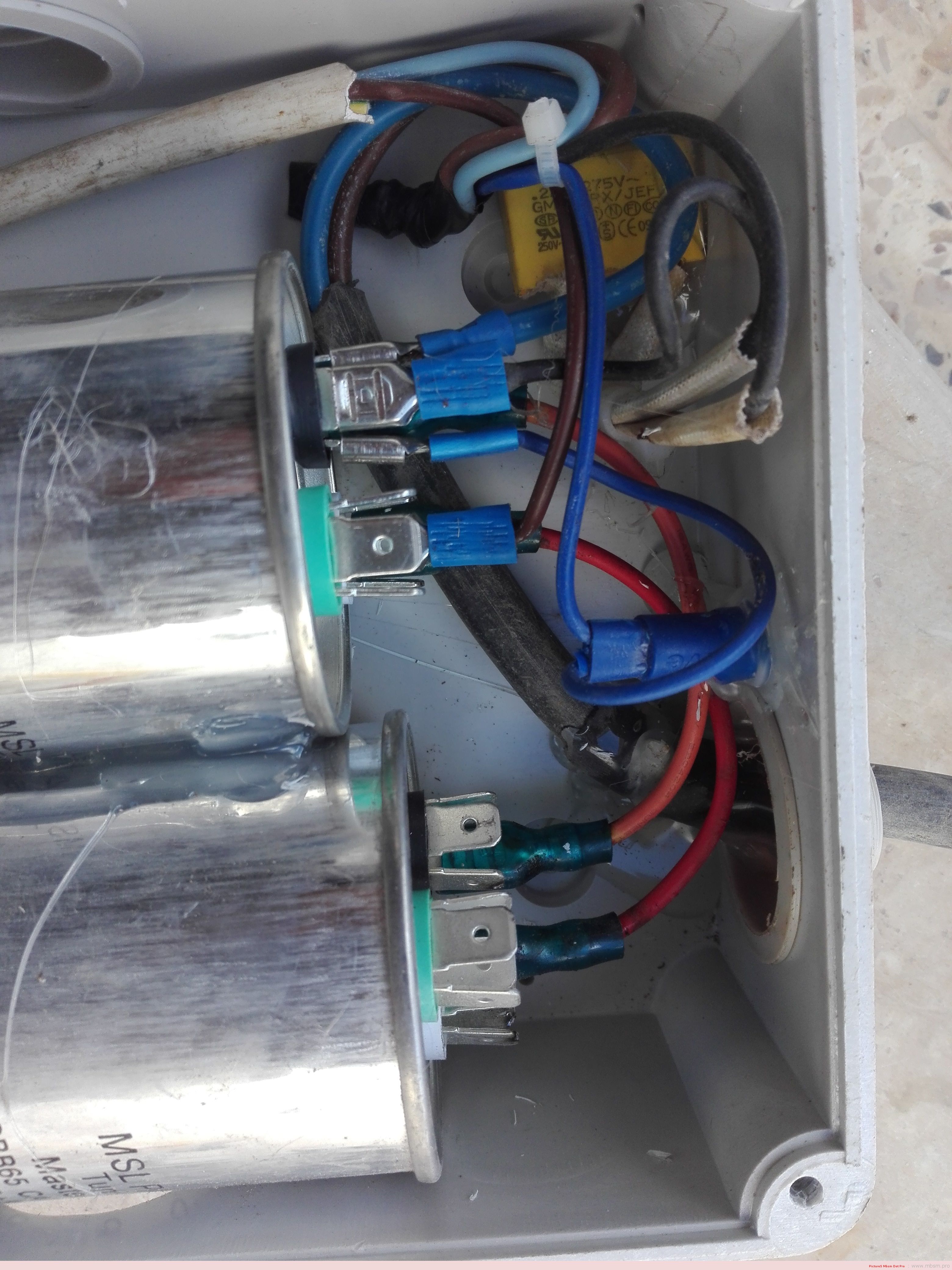
Mbsm.info, File, PDF, Air conditioner, GNF-M30000, GNF M30000, SH General, 30000 Btu, 2.5 Ton, 29.4 bar, 15 A, 220v 1 PH, 3360 W, environment T, R22, 2.5 Kg (GAZ)
Category: Files
written by www.mbsm.pro | 31 March 2022
Mbsm.info, Air conditioner, GNF-M30000, GNF M30000, SH General, 30000 Btu, 2.5 Ton, 29.4 bar, 15 A, 220v 1 PH, 3360 W, environment T, R22, 2.5 Kg (GAZ)
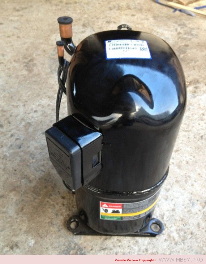
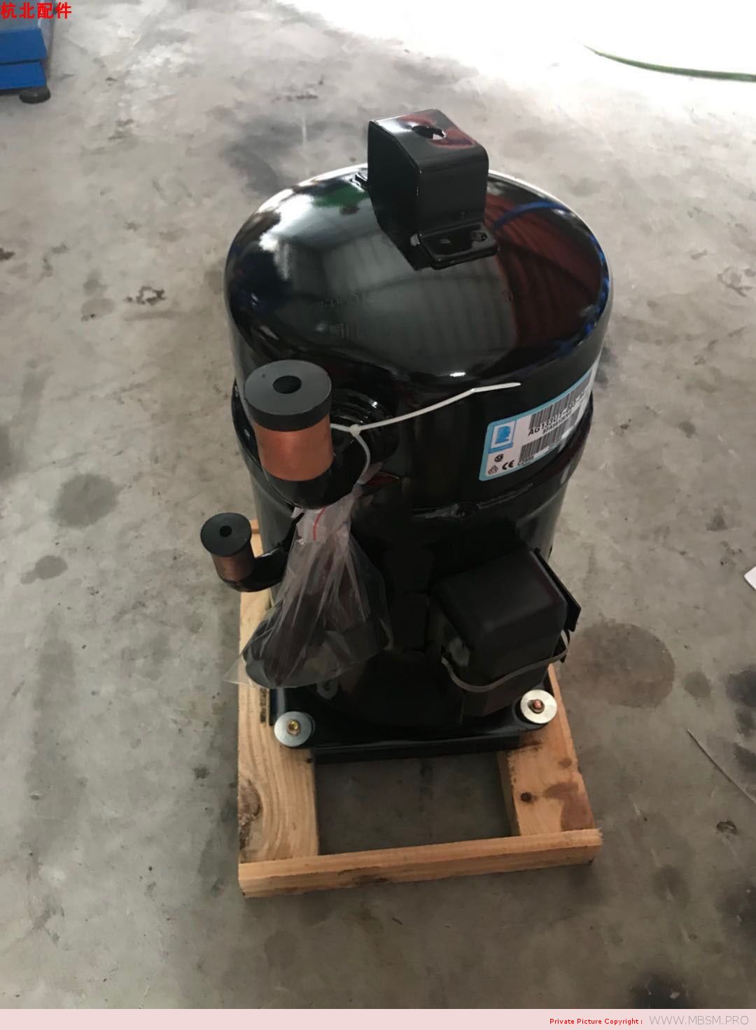
Copeland Model is from 2HP-30JP with high machining accuracy and numerous advantages: small volume, light weight, high efficiency, low vibration and high reliability which will largely replace the traditional piston compressor and has been widely used in the developed countries.
1.With high and low voltage protection, relief valve, the motor overload protection device etc.
2.Easier maintenance, longer service life, design life of 15 years.
3.No internal reciprocating motion mechanism, so the simple structure, small volume, light weight.
4.Less Parts (especially vulnerable part), all parts are sealed inside the acoustic enclosure, at the bottom of the compressor is equipped with elastic damping device; Minimize the noise problem.
5.Torque changes little, high balance, little vibration, stable running, within the scope of its adaptive capacity have higher efficiency.
6.Compact structure, light weight, large capacity, power consumption province, can work continuously for a long time.
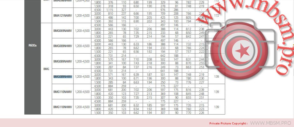
Compressor
Code
Capacity
Input
Current
Weight
Height
Norminal
Power
Power Supply
BTU
W
KW
A
kg
mm
HP
CR37KQ
27000
9170
3.13
9.4
31.8
376
3
220V/380V
50HZ-60HZ
CR47KQ
31500
11300
3.81
11.5
33.6
388
3.5
220V/380V
50HZ-60HZ
CR53KQ
36000
12400
4.3
12
33.6
388
4
220V/380V
50HZ-60HZ
CRGQ-0250
22500
7850
2.76
8.52
30.4
375
2.5
220V/380V
50HZ-60HZ
CRHQ-0275
24750
8200
2.89
9.38
30.4
375
2.75
220V/380V
50HZ-60HZ
CRJQ-0300
27000
9170
3.13
10.23
31.8
381
3
220V/380V
50HZ-60HZ
CRPQ-0450
40500
13400
4.56
14.6
38.1
428
4.5
380V
50HZ-60HZ
CRNQ-0500
45000
15000
5.02
13.4
38.1
409
5
380V
50HZ-60HZ
QR90K1
67500
21700
7.58
22.1
67.6
468
7.5
380V
50HZ-60HZ
QR12M1
90000
28200
10.1
29.5
69.4
468
10
380V
50HZ-60HZ
QR15M1
108000
34900
12.9
38.6
72.6
468
12
380V
50HZ-60HZ
Description
Copeland Hermetic Compressor CRJQ-0300-PFV
Note: Product image may vary and is for your reference only.
Get to know our wide range of Copeland Hermetic Compressors, Copeland Semi-Hermetic Compressors, Copeland Discus Compressors, Copeland Scroll Compressors (Tandem and trio), and Copeland Screw Compressors. We have for sale all its components, accessories and parts for their repair and replacement.
We have Repair and Remanufacturing in Semi-hermetic and Screw-type models.
Copeland Hermetic Compressor CRJQ-0300-PFV
Technical Data CRJQ-0300-PFV
HCFC, R-22, 50 Hz, 1 -phase, 200 V
Air conditioning
Performance
Evaporator Temp(ºF) 45 45
Condensing Temp(ºF) 130 100
Return Gas (ºF) 65 65
Liquid Temp (ºF) 115 85
Capacity (Btu/hr) 31200 42300
Power (W): 3130 2600
Current (Amps): 16.9 14.2
EER (Btu/Wh): 10.0 16.3
Mass Flow (Ibs/hr): 457 545
Sound Data
Sound Power (dBA): 72 Avg 77 Max
Vibration (mils(peak-peak)): 1.8 Avg 2.8 Max
Record Date: 2004-08-19
Mechanical
Displ(in^3/Rev): 4.18
Displ(ft^3/hr): 420.47
Overall Length (in): 9.44
Overall Width (in): 9.13
Overall Height (in): 14.81
Mounting Length (in): 7.50
Mounting Width (in): 7.50
Mounting Height (in): 15.19*
Suction Size (in): 3/4 trozo
Discharge Size (In): 3/8 trozo
Initial Oil Charge (oz): 55
Oil Recharge (oz): 51
Net Weight (ibs): 69.0
Internal Free Volume (in^3): 395.0
Horse Power: NA
*Overall compressor height on Copeland Brand Product´s specified mounting grommets.
Electrical
LRA-High*: 93.0
LRA Low *: NA
LRA-Half Winding: NA
MCC (Amps): 31.5
Max Operating Current: NA
RLA(=MCC/1.4;use for contactor selection): 22.5
RLA(=MCC/1.56;use for breaker & wire size selection): 20.2
RPM: 2900
UL File No: SA-2337
UL File Date: 1984-12-28
*Low and High refer to the low and high nominal voltage ranges for which the motor is approved.
Mbsm.pro, IRF830 MOSFE , in power seplay , old Fortec star 3000
Category: Développement,electronique
written by www.mbsm.pro | 31 March 2022
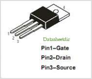
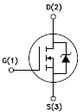
Type Designator: IRF830
Type of Transistor: MOSFET
Type of Control Channel: N -Channel
Maximum Power Dissipation (Pd): 100 W
Maximum Drain-Source Voltage |Vds|: 500 V
Maximum Gate-Source Voltage |Vgs|: 20 V
Maximum Gate-Threshold Voltage |Vgs(th)|: 4 V
Maximum Drain Current |Id|: 4.5 A
Maximum Junction Temperature (Tj): 150 °C
Drain-Source Capacitance (Cd): 800 pF
Maximum Drain-Source On-State Resistance (Rds): 1.5 Ohm
Package: TO220
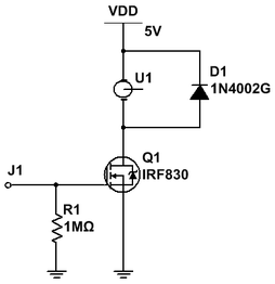
Use the motor voltage and current specifications (either from the data sheet or from experimentation) to determine which transistors to choose. Selecting transistors with greater capacity will provide a margin of safety in your design.
For the purposes of this tutorial, I am using motors specified at 6V where they draw approximately 130mA. I will choose transistors I happen to have in my parts box. If I didn’t have anything on hand that would work, I would buy something that could handle 2X the voltage and current.
The IRF830 is an E-Mode N-channel MOSFET rated at 500V with an continuous current rating of 4.5A and a pulsed current rating of 18A. This is more than adequate for these motors.
It also has an internal diode for back-EMF protection.
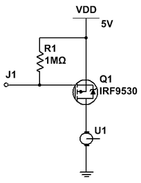
The IRF9530 is an E-Mode P-channel MOSFET rated at 100V with a continuous current rating of 7.5A and a pulsed current rating of 48A. It is also more than adequate for my needs.
It also has an internal diode of back-EMF protection.
The pin out of the IRF9530 if the same as that of the IRF830 – Gate = pin 1; Drain = pin 2; Source = pin 3 (when viewed from the front.)
Motor connected from +V to transistor
Always use an N-channel MOSFET when the transistor is directly connected directly to either -V or GND. In this configuration, the transistor’s source pin sinks current from the motor directly back to the power supply. A HIGH on the Gate turns the transistor ON.
D1 is an added external diode to offer the transistor back-EMF protection. It is not required when using a transistor such as the IRF830 because it already has an internal diode for the same purpose. It is shown here simply to show how it should always be connected when using a transistor without an internal diode. It will be omitted from future circuits unless necessary.
R1 is a pull down resistor to ensure a LOW signal to the gate unless it is specifically driven HIGH.
Connections: Drain to motor; Source to GND; Gate to control device.
J1 (the MOSFET gate) is typically connected to a micro-controller pin. A HIGH signal turns the MOSFET ON energizing the motor; a LOW signal turns the MOSFET OFF stopping the motor – LOW = motor OFF; HIGH = motor ON.
The advantage of this circuit is its simplicity; the disadvantage of this circuit is that the motor can only turn in one direction making it suitable for controlling a fan or pump, but, not for a reversible robot.
Motor connected from transistor to -V/GND
Always use a P-channel MOSFET when the transistor is directly connected to +V. In this configuration, the transistor’s drain pin channels current to the motor from where it will return to the power supply. A LOW on the Gate turns the transistor ON.
R1 is a pull up resistor to ensure a HIGH signal to the gate unless it is specifically driven LOW.
Connections: Drain to motor; Source to +V; Gate to control device.
J1 (the MOSFET gate) is typically connected to a micro-controller pin. A LOW signal turns the MOSFET ON energizing the motor; a HIGH turns the MOSFET OFF stopping the motor – LOW = motor ON; HIGH = motor OFF.
The advantage of this circuit is its simplicity; the disadvantage of this circuit is that the motor can only turn in one direction making it suitable for controlling a fan or pump, but, not for a reversible robot.
Depending upon desired motor response to specific logic levels, either of these circuits is well suited to function as described above.
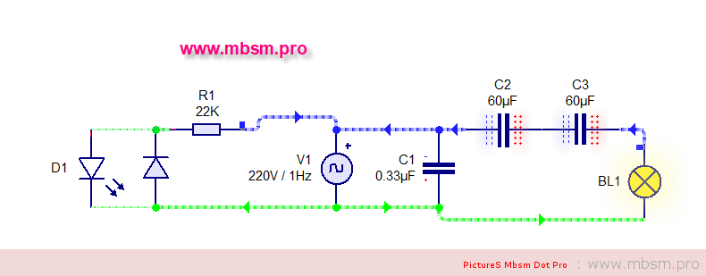
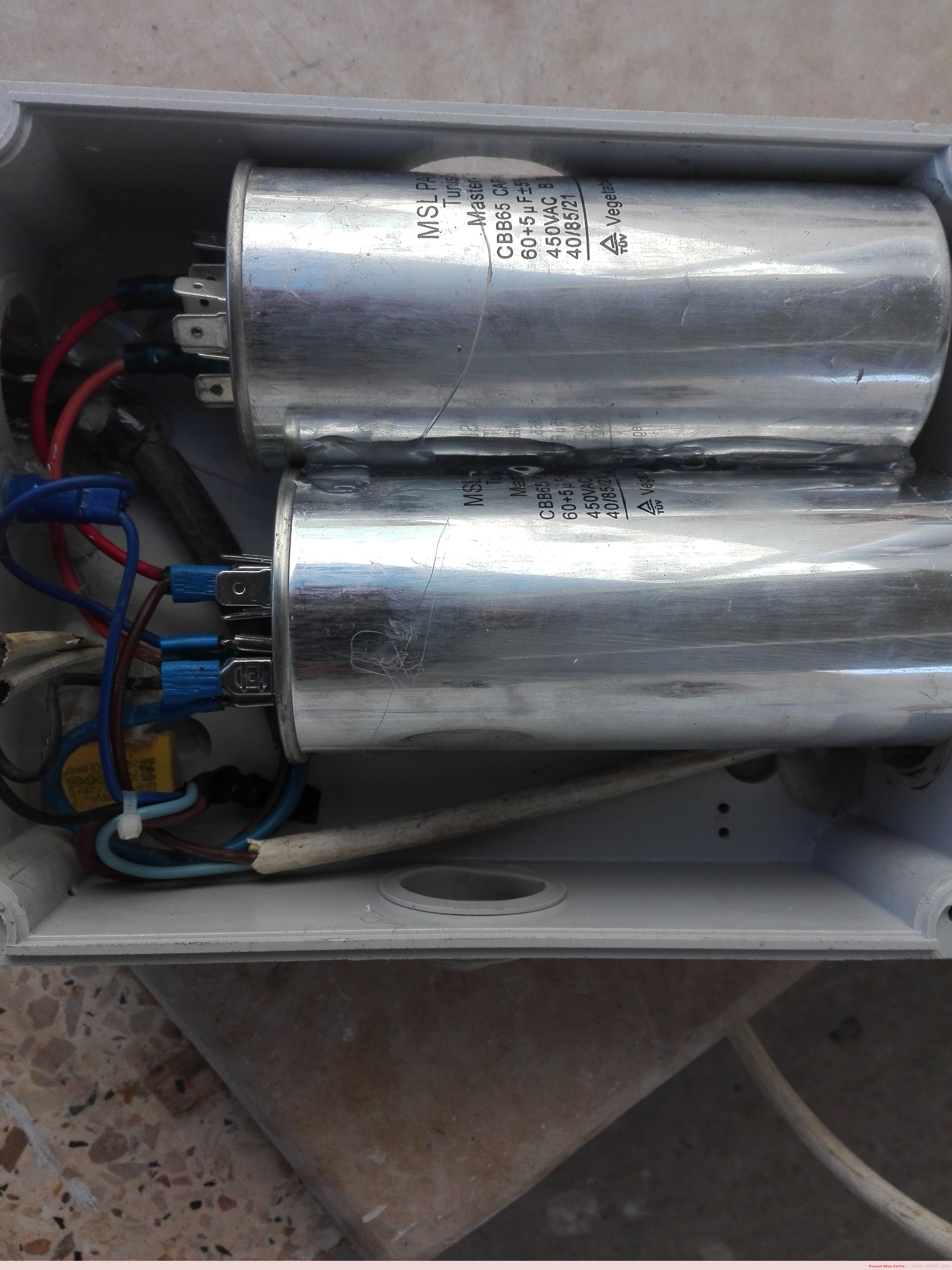
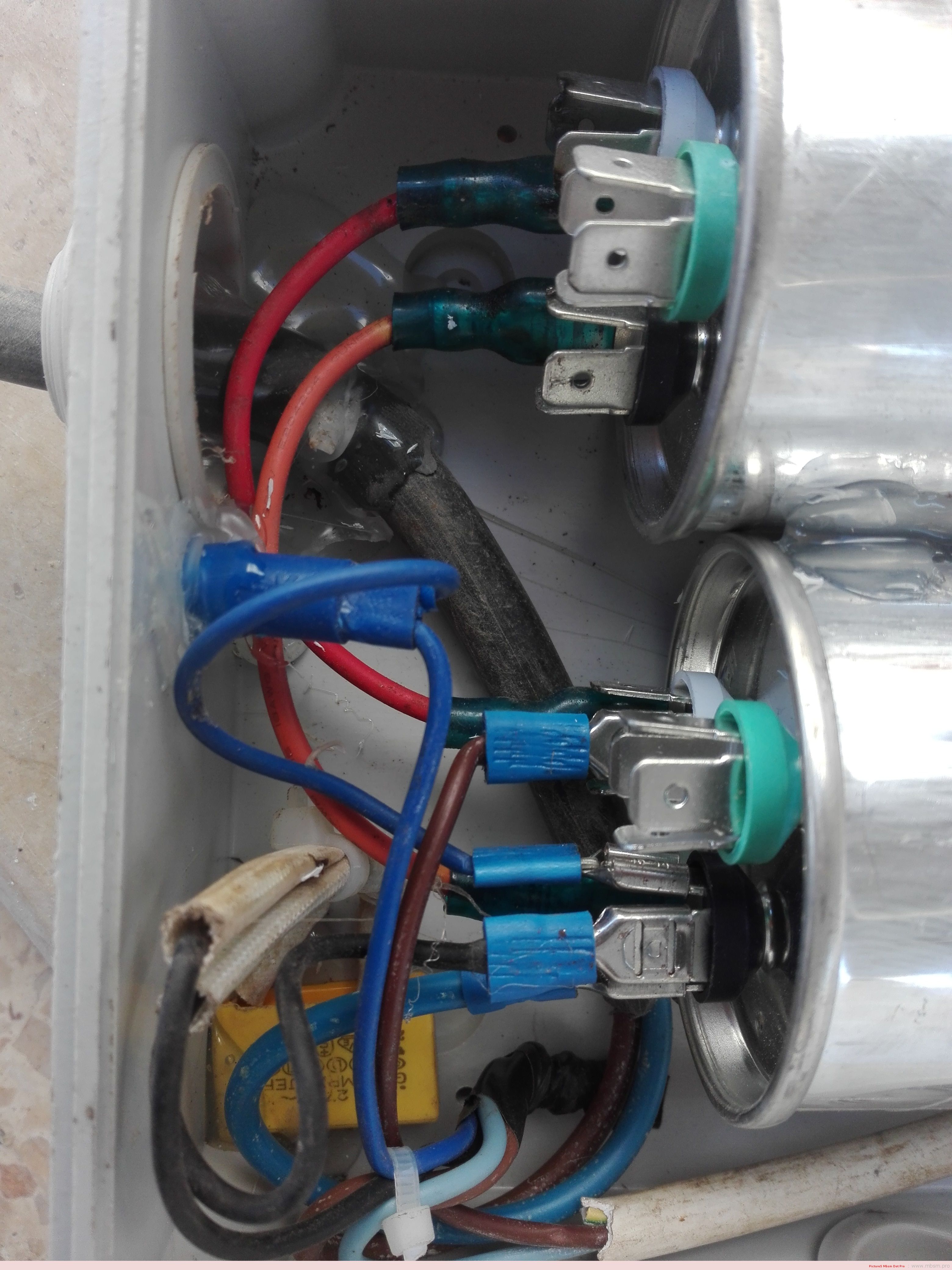
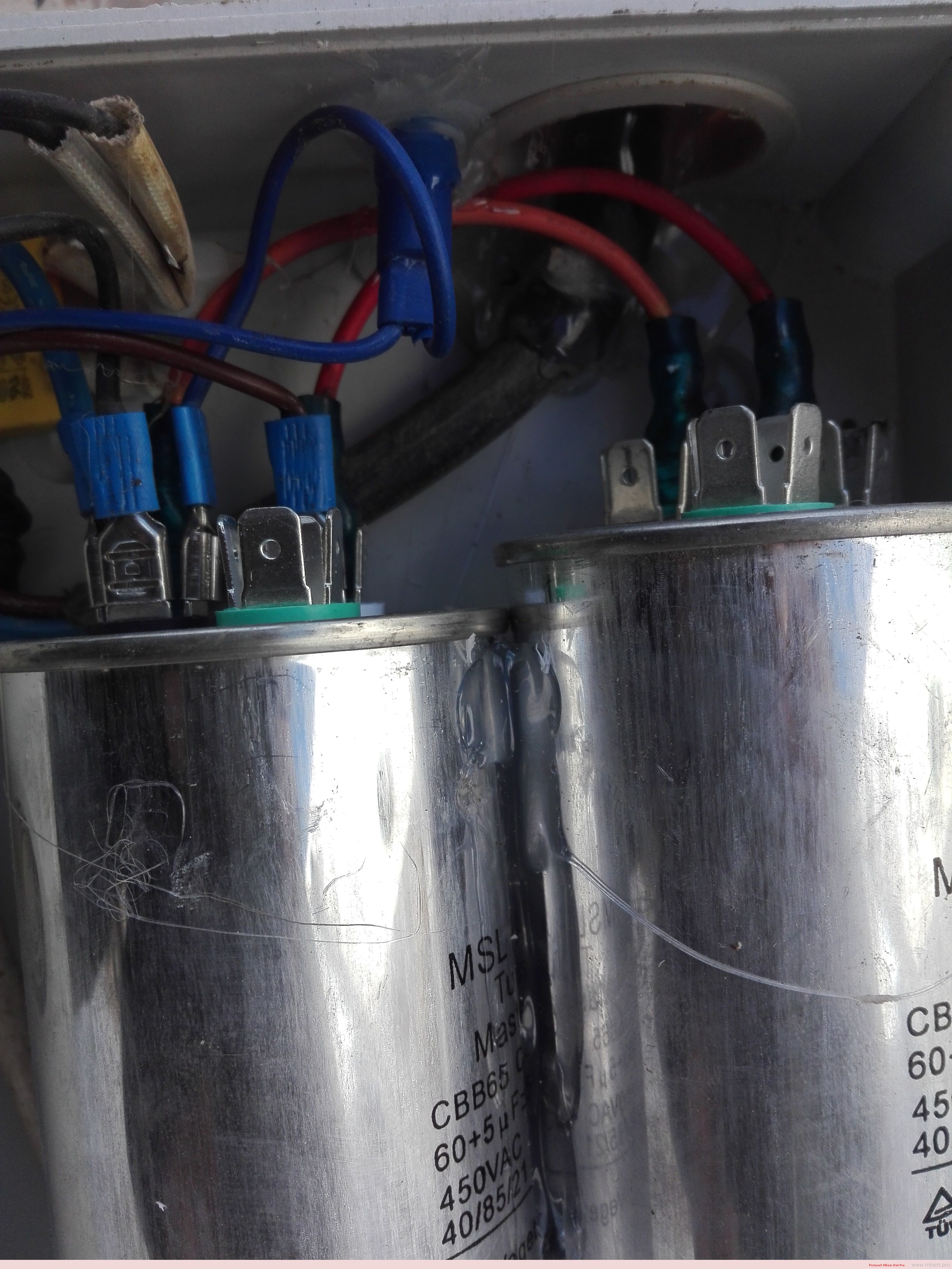
Mbsm.pro, Retardateur d’ampérage de démarrage , Exécution de 3000 W sur un ampérage max 10 a
Category: Invention,Technologie
written by www.mbsm.pro | 31 March 2022
Mbsm.pro, Retardateur d’ampérage de démarrage , Exécution de 3000 W sur un ampérage max 10 a
3000 w = 3000/220 v= 13.636 a
le but c’est démarrer une machine 3000 W sous un disjoncteur 10 A