Bitzer 4J‑13.2Y‑40P Compressor: How to Read and Use the Nameplate Data
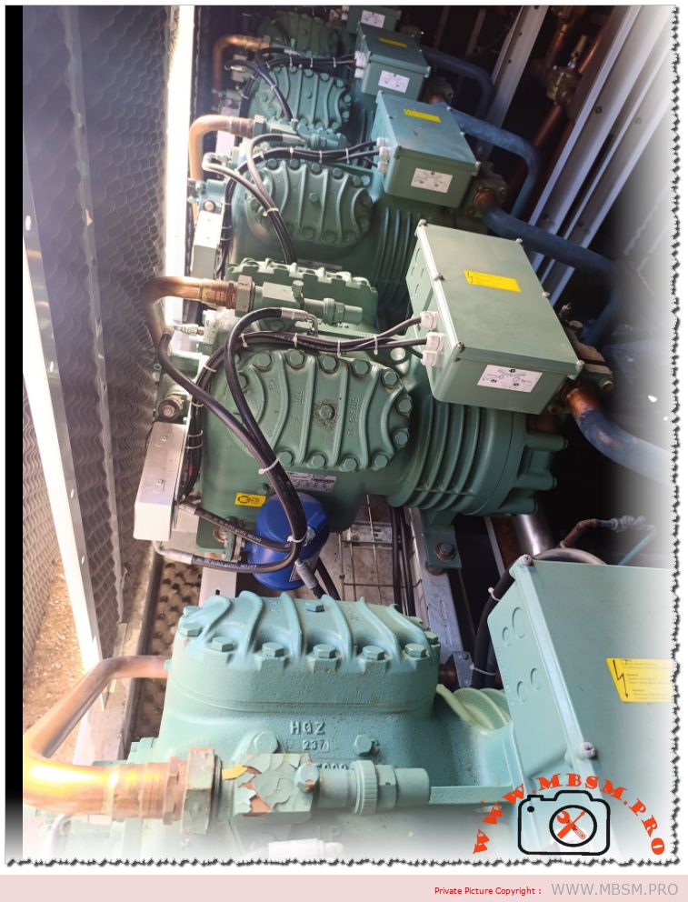
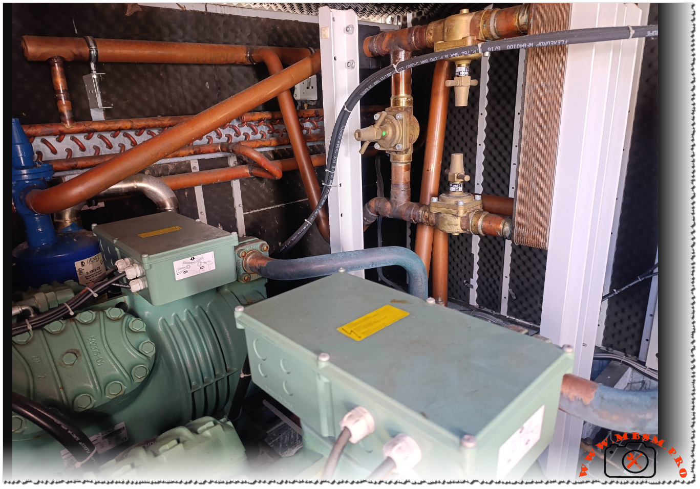
The Bitzer 4J‑13.2Y‑40P is a semi‑hermetic reciprocating compressor widely used in commercial refrigeration and process cooling installations around the world. It is designed for three‑phase power supplies and offers reliable operation in medium‑ to high‑temperature applications. Understanding its nameplate is essential for safe commissioning, correct electrical connection, and accurate system sizing.
Electrical characteristics
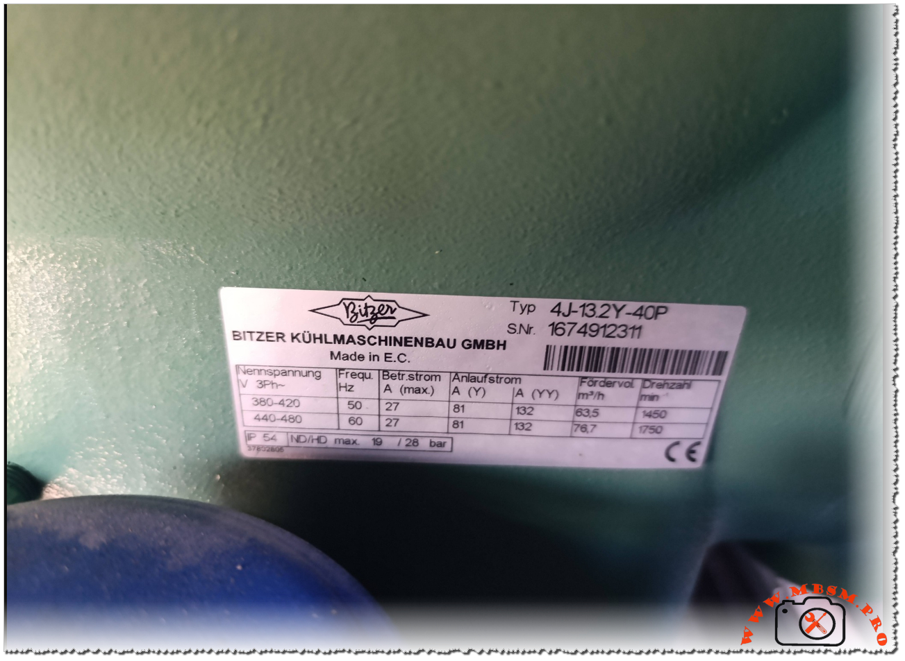
The identification plate lists the nominal three‑phase voltage ranges of 380–420 V at 50 Hz and 440–480 V at 60 Hz, showing that this model is suitable for international grids and export equipment. This flexibility allows installers to deploy the same compressor frame in regions with different mains standards, provided the motor protection and wiring are adjusted accordingly.
At 50 Hz, the maximum running current is specified at 27 A, while the starting current in star (Y) connection reaches 81 A and in part‑winding (YY) configuration 132 A. At 60 Hz, the maximum running current remains 27 A, but the higher frequency increases the starting demand and speed, so the electrical design of contactors, circuit‑breakers and cables must respect these values.
Key electrical data
Parameter
50 Hz value
60 Hz value
Nominal voltage
380–420 V
440–480 V
Max. running current
27 A
27 A
Starting current (Y)
81 A
81 A
Starting current (YY)
132 A
132 A
Performance and operating limits
The nameplate also indicates the theoretical displacement flow rate and motor speed for each frequency. At 50 Hz the compressor delivers 63.5 m³/h at 1450 rpm, while at 60 Hz the flow rises to 76.7 m³/h at 1750 rpm, which directly influences cooling capacity and requires recalculation of expansion valve and piping selections when changing frequency. These figures are important for designers who convert catalog capacities to real site conditions, especially in retrofits where a 50 Hz machine is driven from a 60 Hz supply or via a frequency inverter.
The enclosure rating is IP54, and the plate notes the combination “ND/HD max. 19/28 bar”, indicating the maximum permissible operating pressure on the low‑ and high‑pressure sides of the compressor shell. Respecting these limits is crucial for safety valves, pressure switches and leak testing procedures during commissioning and maintenance.
Performance snapshot
Frequency
Flow rate (m³/h)
Speed (rpm)
Max. shell pressure (ND/HD)
50 Hz
63.5
1450
19 / 28 bar
60 Hz
76.7
1750
19 / 28 bar
Practical guidance for installers
For installers and service technicians, the nameplate of the 4J‑13.2Y‑40P acts as the main reference for electrical protection settings, cable sizing and motor starting method. Checking that the site voltage matches one of the listed ranges is a first step before any connection, followed by the choice between star‑delta, part‑winding or direct‑on‑line starting depending on the available switchgear and network capacity. The running current values help to set thermal overload relays and electronic motor protection units, reducing the risk of nuisance trips or motor damage under heavy load.
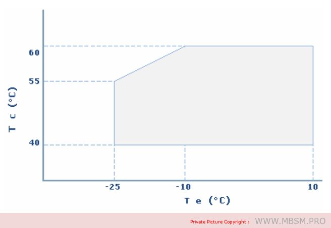
During commissioning, technicians should also compare the actual operating pressures and temperatures with the limits derived from Bitzer’s application range diagrams for this model. This ensures that the compressor runs within its safe envelope when paired with modern refrigerants, oil types and system designs recommended by the manufacturer. Such discipline is especially important for demanding applications like supermarket racks, process chillers and cold‑storage plants where the 4J‑13.2Y‑40P is often installed.
Documentation and further resources
Bitzer provides full technical information, performance curves and motor data sheets for the 4J‑13.2Y‑40P, which complement the basic figures printed on the nameplate. These documents are available in the official digital library and are regularly updated to reflect changes in approved refrigerants, oils and electrical components. Engineers and technicians should always consult the latest documentation before selecting replacement compressors or redesigning existing installations, as updated guidelines may affect allowed operating envelopes and accessory choices.
Refrigerants, Standing, Suction and Discharge Pressures for Modern HVAC Systems
Category: Refrigeration
written by www.mbsm.pro | 28 December 2025
Guide to Common Refrigerants: Standing, Suction and Discharge Pressures for Modern HVAC Systems
Refrigeration technicians today work with a mix of legacy and new-generation refrigerants, each with its own safe pressure range and boiling temperature. Understanding these values is essential for accurate diagnostics, safe charging and long compressor life in air‑conditioning and commercial refrigeration.
Key role of pressure charts
Pressure–temperature charts and standing/suction/discharge tables give technicians a fast reference for what a system “should” be doing at a given ambient or evaporating temperature. Using wrong reference values can lead to over‑charging, overheating, liquid slugging or misdiagnosis of a healthy system as faulty.
Overview of common refrigerants
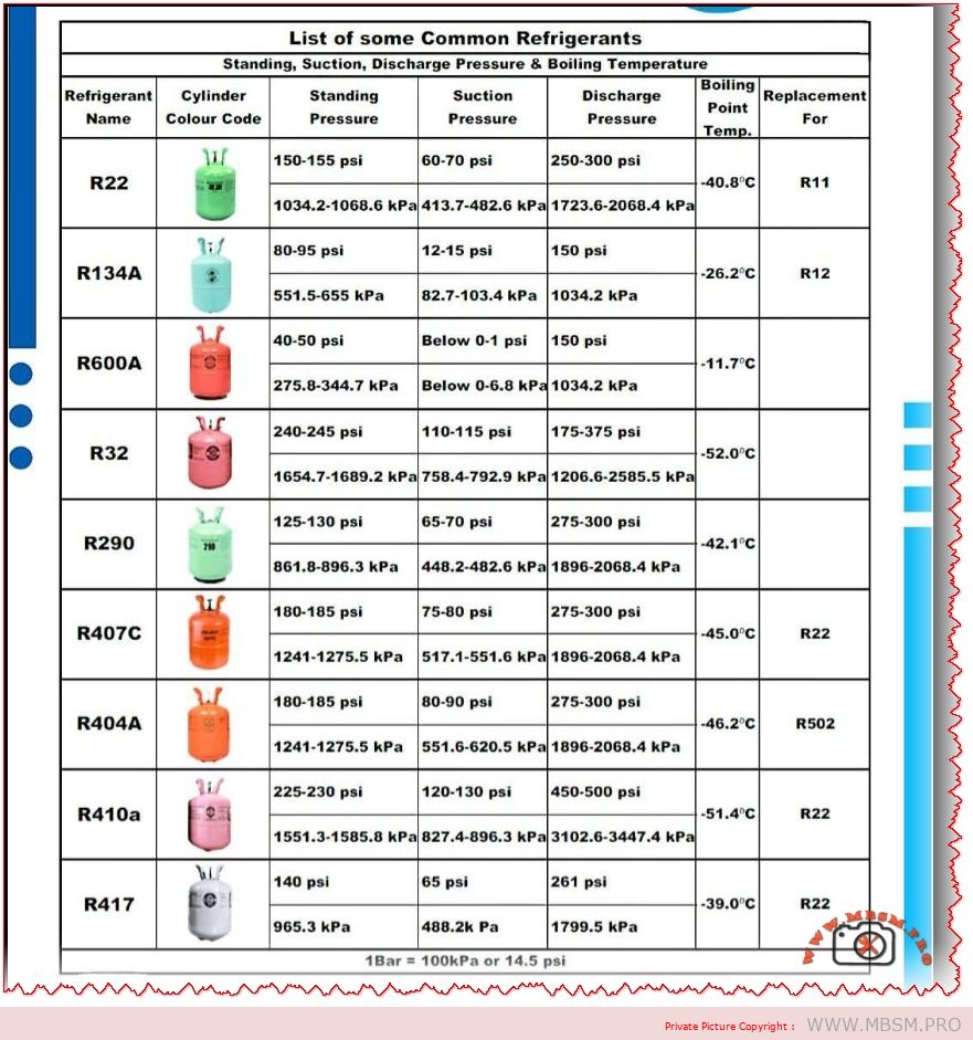
The image groups the most used refrigerants in residential and light commercial systems: R22, R134a, R600a, R32, R290, R407C, R404A, R410A and R417 (R417A). Each gas has a typical standing pressure (static pressure at rest), an evaporating suction pressure, a condensing discharge pressure and a characteristic boiling point at atmospheric pressure.
Typical pressure ranges from the chart
The following table summarises the indicative values shown in the chart (all pressures are approximate, for normally loaded systems at typical comfort‑cooling conditions).
Indicative pressures and boiling points
Refrigerant
Approx. standing pressure
Approx. suction pressure
Approx. discharge pressure
Boiling point (°C)
Typical replacement for
R22
150–155 psi / 1034–1069 kPa
60–70 psi / 413–483 kPa
250–300 psi / 1724–2069 kPa
−40.8 °C
R11 / legacy R22 AC
R134a
80–95 psi / 552–655 kPa
12–15 psi / 83–103 kPa
~150 psi / 1034 kPa
−26.2 °C
R12 in domestic & auto
R600a
40–50 psi / 276–345 kPa
≈0–1 psi / 0–7 kPa
~150 psi / 1034 kPa
−11.7 °C
Low‑charge fridges, R12
R32
240–245 psi / 1655–1689 kPa
110–115 psi / 758–793 kPa
175–375 psi / 1207–2586 kPa
−52.0 °C
High‑efficiency R410A/R22
R290
125–130 psi / 862–896 kPa
65–70 psi / 448–483 kPa
275–300 psi / 1896–2069 kPa
−42.1 °C
R22 in some systems
R407C
180–185 psi / 1241–1276 kPa
75–80 psi / 517–552 kPa
275–300 psi / 1896–2069 kPa
−45.0 °C (bubble)
R22 retrofits
R404A
180–185 psi / 1241–1276 kPa
80–90 psi / 552–621 kPa
275–300 psi / 1896–2069 kPa
−46.2 °C
R502 low‑temp systems
R410A
225–230 psi / 1551–1586 kPa
120–130 psi / 828–896 kPa
450–500 psi / 3103–3447 kPa
−51.4 °C
Modern R22 AC
R417A
~140 psi / 965 kPa standing
~65 psi / 448 kPa suction
~261 psi / 1796 kPa discharge
−39.0 °C
R22 service blend
These figures are not universal “set‑points”, but practical targets that help technicians decide whether a system is under‑charged, over‑charged or suffering airflow or mechanical problems.
Safety, cylinder colours and replacements
Many countries use conventional cylinder colour codes to identify refrigerants quickly on site, although some regions are migrating to neutral colours with clear labelling. Hydrocarbons such as R290 and R600a are flammable, so working pressures must always be combined with strict leak‑prevention, ventilation and ignition‑control procedures.
When phasing out ozone‑depleting R22, blends like R407C or R417A are often used in retrofit projects, while new high‑efficiency equipment typically relies on R410A or R32 with different design pressures. Comparing the standing and operating pressures during commissioning helps ensure that a replacement refrigerant is compatible with existing components such as compressors, valves and heat‑exchangers.
Practical use for technicians and trainers
Technicians can laminate similar tables and keep them in the toolbox or on the workshop wall as a quick‑reference during charging and troubleshooting.
Training centres and HVAC content creators like Mbsmgroup and Mbsm.pro can turn these values into interactive quizzes, infographics or mobile‑friendly charts for students and new technicians.
Mbsm.pro, Understanding, Motor, Starting , Systems, for, Compressor
Category: Chaud&Froid
written by www.mbsm.pro | 28 December 2025
Introduction Motor starting systems are critical in ensuring the efficient and safe operation of electric motors across various industries. Choosing the right starting method can significantly impact performance, energy consumption, and equipment longevity. In this post, we’ll explore the most common motor starting systems, their characteristics, advantages, and disadvantages to help you make informed decisions for your applications.
1. Direct-On-Line (DOL) Starting
Characteristics:
Starting current: 5 to 8 times the rated current.
Starting torque: 0.5 to 1.5 times the rated torque.
Direct connection of the stator to the power supply.
Advantages:
Simple and cost-effective.
No additional devices required.
Disadvantages:
High starting current may cause voltage drops in the network.
Not recommended for high-power motors.
2. Star-Delta Starting
Characteristics:
Starting current: 1.5 to 2.6 times the rated current.
Reduced voltage in star mode (3 times lower).
Requires a motor with compatible windings.
Advantages:
Reduces starting current.
Suitable for machines with low resistive torque or no-load starting.
Disadvantages:
Requires a specific motor type.
Not effective for heavy loads.
3. Part-Winding Starting
Characteristics:
Starting current: Approximately half of DOL starting.
Starting torque: Higher than star-delta.
Uses two parallel windings.
Advantages:
Lower starting current.
Higher starting torque compared to star-delta.
Disadvantages:
Rarely used in Europe.
Requires a motor with specific windings.
4. Stator Resistance Starting
Characteristics:
Starting current: 4.5 times the rated current.
Starting torque: 0.75 times the rated torque.
Resistors in series with the windings.
Advantages:
Reduces starting current.
No winding modification required.
Disadvantages:
Energy losses in resistors.
Requires a timer to remove resistors.
5. Autotransformer Starting
Characteristics:
Reduced voltage during starting.
Three stages: star, partial coupling, and full voltage.
Selectable transformation ratio.
Advantages:
Reduces starting current.
Flexible voltage selection.
Disadvantages:
Expensive and complex.
Requires additional space for the autotransformer.
6. Electronic Soft Starter
Characteristics:
Limits current and adjusts torque.
Smooth start and stop.
Electronic control of applied voltage.
Advantages:
Smooth starting reduces mechanical stress.
Energy savings.
Disadvantages:
Higher initial cost.
Requires maintenance of the electronic system.
7. Variable Frequency Drive (VFD) Starting
Characteristics:
Speed and torque control.
Suitable for high-inertia loads.
Optimizes energy consumption.
Advantages:
Precise speed control.
Ideal for applications requiring variable speed.
Disadvantages:
High initial cost.
Requires technical expertise for setup and maintenance.
Conclusion
Selecting the right motor starting system depends on factors such as motor size, load type, and operational requirements. While DOL starting is simple and cost-effective, more advanced systems like soft starters and VFDs offer greater control and efficiency, albeit at a higher cost. Understanding these systems will help you optimize performance, reduce energy consumption, and extend the lifespan of your equipment.
If you have any questions or need further assistance in choosing the right motor starting system for your application, feel free to leave a comment or contact us!
Tags: Motor Starting Systems, Electric Motors, Soft Starters, VFD, Star-Delta Starting, Industrial Automation Categories: Electrical Engineering, Industrial Automation, Energy Efficiency
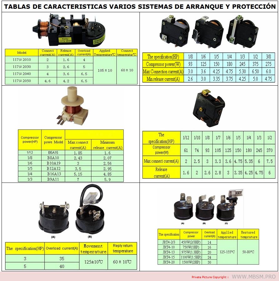
table organizes the information for better readability and understanding:
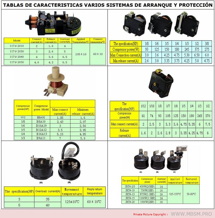
Content Table: Motor Starting Systems and Protection Specifications
1. General Specifications
Model
Concesor Current (A)
Relaxo Current (A)
Overload Current (A)
Applied Temperature (°C)
Concesor Temperature (°C)
1171/2010
2
1.6
4
–
–
1171/2030
3
2.6
5
105 ± 10
60 ± 10
1171/2040
4
3.6
6.5
–
–
1171/2050
4.6
4.2
6.5
–
–
2. Compressor Power Specifications (HF)
Component Power (HF)
Compressor Power Model
Max. Connection Current (A)
Minimum Release Current (A)
1/12
BSA15
1.55
1.6
1/8
BSA10
2.43
2.07
1/6
B10A19
3
2.56
1/5
B12A12
3.5
2.95
1/4
B16A13
5.15
4.85
1/3
B9A11
7
5.9
3. Compressor Power and Current Ratings
Component Power (HF)
Compressor Power (W)
Max. Connection Current (A)
Release Current (A)
1/12
61
2
1.6
1/10
74
2.5
2
1/8
93
3
2.6
1/7
105
3.3
2.8
1/6
125
3.6
3
1/5
150
4.75
3.35
1/4
180
5.35
4.25
1/3
245
6
4.75
1/2
370
7.5
6
4. IRFA Series Specifications
Model
Compressor Power (W)
Max. Connection Current (A)
Release Current (A)
IRFA-20
450W (20HF)
14
–
IRFA-10
750W (1HF)
16
–
IRFA-13
975W (1HF)
20
–
IRFA-15
1100W (2HF)
24
–
IRFA-20
1500W (2HF)
30
–
5. Additional Notes
Concesor Current: The current drawn by the compressor during operation.
Relaxo Current: The current at which the system releases or disconnects.
Overload Current: The maximum current the system can handle before tripping.
Applied Temperature: The operating temperature range for the system.
Concesor Temperature: The temperature range for the compressor during operation.
This table provides a clear and organized overview of the motor starting and protection systems, including their specifications and performance metrics. Let me know if you need further assistance!
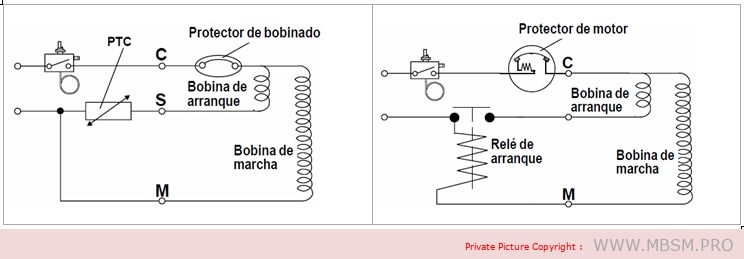
Sistemas de arranque:
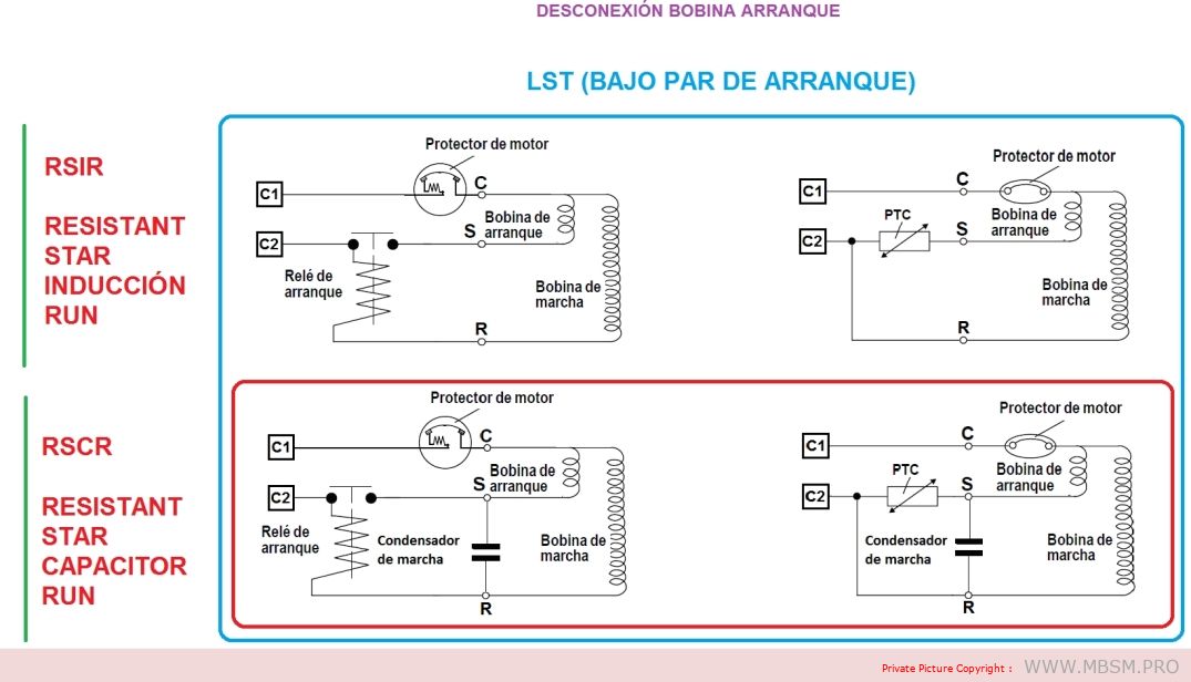
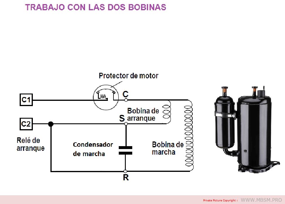
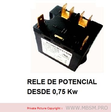
En el caso del relé de arranque, cuando la energía es aplicada al compresor, la bobina solenoide del relé atrae la armadura del mismo para arriba produciendo el cierre de los contactos, energizando la bobina de arranque del motor. Cuando el motor del compresor alcanza la velocidad de funcionamiento, la corriente de la bobina principal del motor será tal que la bobina solenoide del relé desenergiza permitiendo que los contactos del relé se abran, desconectando de esta manera la bobina de arranque del motor.
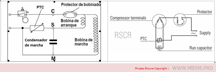
The PTC is a semiconductor with a positive temperature coefficient, which means that it offers no resistance to the passage of current when the unit is cold. When the unit is turned on, the current passing through the PTC causes it to heat up rapidly, creating such a high resistance in its circuit that the passage of current remains at a very low value but high enough to keep the PTC warm.
Prerequisites for using the PTC system:
– The thermostat must be used to ensure that the stop time allows for pressure equalisation in the system. – Depending on the size of the compressor, the stop period should be at least 3 to 5 minutes (e.g. the minimum times for TL are 3 minutes, and for SC 5 minutes).
The PTC system offers a number of advantages:
– Improved protection of the starter coil – PTC is not affected by voltage increases or decreases – Free from radio and television interference – No wear – Identical PTC starter system for many compressors of different sizes.
LST (low starting torque) engines
Compressors with RSIR and RSCR system motors have a low starting torque (LST) and are used in refrigeration appliances with capillary tubes, where pressure equalization takes place before each start.
The RSIR system incorporates a PTC thermistor or a relay and a bifilar winding (current relay) as starting equipment. The PTC needs to be kept off for a period of about 5 minutes to allow it to cool down before it can restart.
RSCR (Resistant Start Capacitor Run): Induction motor with resistor start and run capacitor.
The RSCR system, consisting of a PTC thermistor and a run capacitor, is mainly used in energy-optimized compressors.
HST (High Starting Torque) Engines
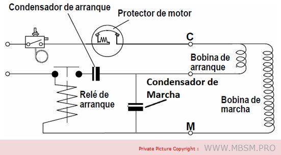
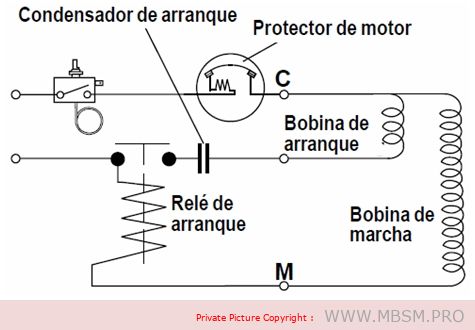
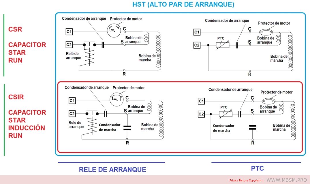
Compressors with CSIR and CSR type motors have a high starting torque (HST) and can be used in refrigeration appliances with capillary tubes as well as in systems with expansion valve operation (without pressure equalization).
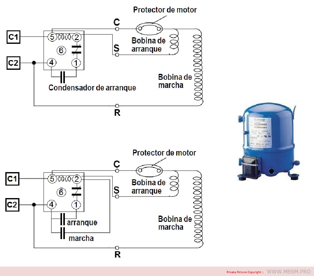
– CSR (Capacitor Start Run): Induction motor with start capacitor and run capacitor
CRS systems require a voltage relay, a start capacitor and a run capacitor.
– CSIR (Capacitor Start Induction Run): Induction motor with starting capacitor.
The CSIR system consists of the starting relay and starting capacitor specified for each particular compressor type.
Graphic summary:
Conditions for a long service life
To achieve trouble-free operation and long service life of the hermetic compressor, the following conditions must be met:
1. The starting torque must be sufficient to enable the motor to start under the prevailing pressure conditions in the system. 2. The maximum torque of the motor must be sufficient to enable the motor to withstand the load conditions at start-up and during running. 3. During operation of the refrigeration system, the temperature of the compressor must never rise to levels that could damage its components. Condensation and compression temperatures must therefore be kept as low as possible. 4. Correct sizing of the refrigeration system in question, and a correct assessment of the operating conditions of the compressor under maximum loads. 5. Sufficient cleanliness and minimum residual moisture in the system.
Engine overload
The motor start-up is determined by the starting torque and/or the maximum torque of the motor. If the starting torque or the maximum torque are insufficient, the compressor cannot start or the start-up will be hindered and delayed due to the activation of the internal motor protector.
Repeated starting attempts subject the motor to overload, which will sooner or later result in failure. It is all a matter of selecting the right compressor for extreme working conditions.
Thermal overload
To ensure a long compressor life, operating conditions that lead to thermal decomposition of the materials used in the compressor must be avoided. The materials involved are coolant, oil and materials for motor insulation. Motor insulation consists of enamel for the copper winding, insulation for the stator core slot, insulating tape and power cables.
The R 134a, R 404A or R 507 refrigerants used today require advanced oils. Only special quality POE oils (polyester) are used.
For the application of compressors in domestic and commercial refrigeration devices with the refrigerants that are currently available, it is advisable to comply with the following rules.
Coil temperature
The coil temperature must never exceed 125°C during continuous operation. For limited periods of time, e.g. during compressor start-up or in case of short load peaks, the temperature should not exceed 135°C.
For commercial refrigeration with R 134a, the same values apply as for domestic refrigeration. However, cooling the compressor by means of a fan is recommended.
Condensation temperature
When using R 600a or R 134a refrigerants, the condensation temperature during continuous operation must not exceed 60°C. During short load peaks, the temperature must not exceed 70°C.
In commercial refrigeration where R 404A and R 507 refrigerants are used, the condensation temperature limit is 48°C during continuous operation and 58°C during peak loads.
Checking the compressor coils.
We must take into account that we are going to check an electromechanical part since it has an electrical part that makes another mechanical part work and it is necessary to carry out several types of tests to be able to determine if it is damaged and if it is possible to find out which part of the compressor is damaged. For these tests we will need measuring tools and a little expertise since in some we will use the senses, we will divide the tests into two parts, one when it is installed and the other when the compressor is alone without being installed.
Measure continuity between the compressor coils:
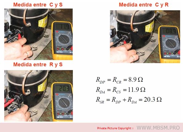
For this test we will need a tester that measures continuity, we will have to disconnect the compressor cables, the test consists of verifying that there is continuity between the compressor terminals and measuring two by two we verify if there is no continuity in these terminals, we must take into account the temperature of the compressor, if it is cold the coil is open (damaged), if the compressor is hot we must wait for it to cool down because it may be that the thermal switch is open due to high temperature and we perform the test again.
If you are disconnected or off the computer, this test is performed in the same way.
Test if the amperage is too high:
For this test we will need a clamp meter and we will place it in one of the compressor lines, either the common one, preferably the start (maintenance) line, it should not be placed on the start-up line because it will not give us the measurement we need to check, we must know the normal working amperage of the compressor, start it, wait for it to stabilize, at start-up it normally consumes 5 times the working amperage, we wait for it to stabilize and if it is above that indicated on the plate it is too high in amperage, in this case we will have to check, capacitor, ventilation, pressures, voltage tension, to determine if it is because of the compressor or an external cause. If the compressor is disconnected from the equipment and the amperage exceeds that indicated it is a sign that it is damaged and we should not install it.
Determine if compressor pumps well:
Pressure test: it is not advisable to measure the output pressure, however there are technicians who when buying a used compressor usually measure the high pressure, if it exceeds 300 psi the compressor is fine and if when turning it off the pressure is maintained without it returning, it is an excellent sign that everything is fine, it is not low on compression since the valves do not return pressure, this test is not performed on rotary compressors because they work with the pressure and temperature of the same compressor to reach the normal working refrigerant gas pressure.
If the compressor is installed when measuring with the pressure gauge and registering that the high pressure does not rise and the low pressure is very high, it is a sign of decompression. If it is a rotary equipment, we look at the suction filter that is located at the compressor inlet to see if it freezes. If it is frozen it is due to obstruction. If, upon observing this, everything is normal, it is most likely that the pressures are destabilized due to low compression. Another sign is that the amperage with the low pressure high and the high pressure low will show a consumption well below normal since it is not exerting force to maintain a high pressure in the condenser.
Determine if the compressor is seized:
For this we need to use the ammeter or clamp meter when trying to start the having a suitable capacitor and in good condition it should not exceed the starting amperage which is 5 times the nominal or working amperage, if it exceeds it is a sign that it is blocked, we can use an additional starting aid to the capacitor and if with this the result is the same (taking into account that the voltage is normal) we will determine that the compressor is seized and it is necessary to replace it.
When I mention at the beginning that we should use our senses, I mean that if we are testing a compressor and we notice a strange noise when starting it, this is not a good sign, and if it is already in full operation and sounds unusual, it is a bad sign, as well as looking at the part where the cables are connected to the compressor, since this is a seal that sometimes gets damaged and allows oil to leak, be attentive and verify that the filter that is fixed by a belt in the case of rotary compressors is not subject to this belt being damaged, since it also produces noise, refrigerant gas leaks and vibrations, these are details that we should be very attentive to.
Note: We should always try to exhaust every last resource to determine if a compressor is damaged, because if we are technicians and they seek a second opinion, and it works in the hands of the second opinion, the client will think the worst of us and our reputation will be in jeopardy, and if the compressor is our property, we should also exhaust all resources, since it is the most expensive part of our air conditioning, both its individual price and the expenses generated in labor and materials for its installation. We must be very clear that it no longer works for ourselves and for others.
Checking the starting capacitor.
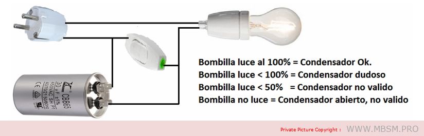
To test a starting capacitor in a simple way, we simply connect it in series with an incandescent light bulb and supply it with AC voltage. We will also complement the assembly with a normally open push button like the one used in doorbells, which we will connect in parallel with the capacitor according to the following diagram.
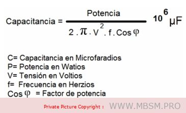
Calculation of the starting capacitor capacity:
Many refrigeration compressors are single-phase motors. The problem with supplying a motor with 230 V, with a single phase, means that the torque needed for starting is not generated. To “trick” the motor and generate a fictitious phase, a capacitor is used that shifts the supply voltage by 90º. In this way, we will have the necessary starting torque. To obtain the best and most powerful starting torque of the single-phase motor, which will result in the refrigeration compressor working better and with more force and not jamming… the capacity of the capacitor that obtains this 90º phase shift must be calculated.
It is not true that the larger the capacitor, the greater the starting torque of the single-phase motor. The only thing that is obtained is a greater phase shift, which will produce a lower starting torque of the single-phase motor. In fact, if the capacitor is too large, it may happen that the phase shift is 360º, that is, 0º, so that the single-phase motor would have no starting torque. In any case, capacitors with a higher or lower capacity than necessary will generate phase shifts lower or higher than the optimum, which will result in starting torque values lower than the optimum. Starting with starting torque lower than the optimum can result in our single-phase motor burning out; it has to make more effort than necessary to start, the intensity increases and the motor burns out, which would end up being damaged.
The highest starting torque for the single-phase motor is obtained when the phase shift we obtain with our capacitor is 90º. To obtain this phase shift we will proceed to calculate the capacitor of a single-phase motor in the following way.
Suppose we have an engine with the following characteristics
Power 150 W Working voltage 230 V. Frequency 50 Hz. Cosine of phi = 0.85
Applying the formula, the capacitance is 10.61 microfarads.
Therefore, the optimal ideal capacitor for the single-phase motor in the example is 10.61 uF, as 10.61 micro Farads is a capacitor value that we cannot find on the market, we will choose to buy the value that is closest in this case 10 micro Farads.
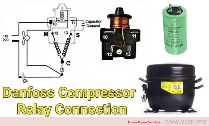
Danfoss Relay Connection Diagram for the Electric Compressor in Refrigeration Systems
Below is a detailed explanation of the components and connection diagram of the Danfoss relay for the electric compressor used in refrigeration systems:
1. Components of the Diagram
Compressor:
The compressor is the heart of the refrigeration system, responsible for compressing the refrigerant (freon) and circulating it through the system.
Relay:
The relay is used to provide additional electrical current to the start terminal (S) of the compressor, helping it start smoothly.
Capacitor:
The capacitor improves the compressor’s torque during startup, reducing the load on the electric motor.
Electrical Circuit Diagram:
The diagram shows how the compressor terminals (C, S, R) are connected to the relay, capacitor, and power source.
2. Compressor Terminal Connections
C (Common):
The common terminal connected to both the run and start windings.
R (Run):
The terminal responsible for continuous operation of the compressor after startup.
S (Start):
The terminal responsible for starting the compressor with the help of the relay and capacitor.
3. Steps to Connect the Relay to the Compressor
A. Connecting the Capacitor:
The capacitor is connected between the S (Start) terminal and the R (Run) terminal to support startup torque.
B. Connecting the Relay:
Terminals 10 and 11:
Connected to the power source and the run resistor.
Terminals 12 and 13:
Connected to the compressor terminals: S (Start) and C (Common).
C. Power Supply:
The circuit is powered by a 110V or 220V source (depending on the system used).
4. How the Relay Works
When power is connected, the relay sends additional current to the start terminal (S) via the capacitor.
Once the compressor starts running, the relay automatically cuts off the current to the start terminal.
The compressor continues to operate through the current flowing to the run terminal (R).
5. Importance of Correct Relay Connection
Compressor Protection:
Ensures safe compressor operation during startup.
Energy Saving:
The relay cuts off the startup current after operation to avoid overload.
Performance Improvement:
Helps stabilize compressor operation.
6. Verification Steps After Connection
A. Checking Terminal Connections (C, R, S):
Use a resistance meter (ohmmeter) to verify correct terminal connections.
B. Testing the Relay:
Ensure the relay sends startup current when powered.
C. Testing the Capacitor:
Measure the capacitor’s capacitance (microfarads) using a capacitor tester.
D. Running the Compressor:
Start the system and check for stable compressor operation.
Listen for noise: If it is loud, there may be a connection error.
7. Common Faults and Solutions
A. Compressor Fails to Start:
Cause: Faulty relay or capacitor.
Solution: Test the relay and capacitor and replace them if necessary.
B. Compressor Runs Briefly and Stops:
Cause: High current or excessive load.
Solution: Ensure the external capacitor is clean and there is proper airflow around the unit.
C. Incorrect Connection:
Cause: Swapped terminals (C, R, S).
Solution: Use a resistance meter to accurately identify the terminals.
8. Important Tip
Ensure:
Terminals are connected correctly according to the diagram.
Use a capacitor that matches the compressor’s specifications.
Test the relay before installation to ensure no internal damage.
Conclusion
Correctly connecting the Danfoss relay is crucial for ensuring safe and efficient compressor operation in refrigeration systems. Follow the diagram carefully and perform the necessary tests to avoid malfunctions and improve system performance.
Mbsm.pro, Tecumseh, Compressors, R134a, M/HBP
Category: compressor
written by www.mbsm.pro | 28 December 2025
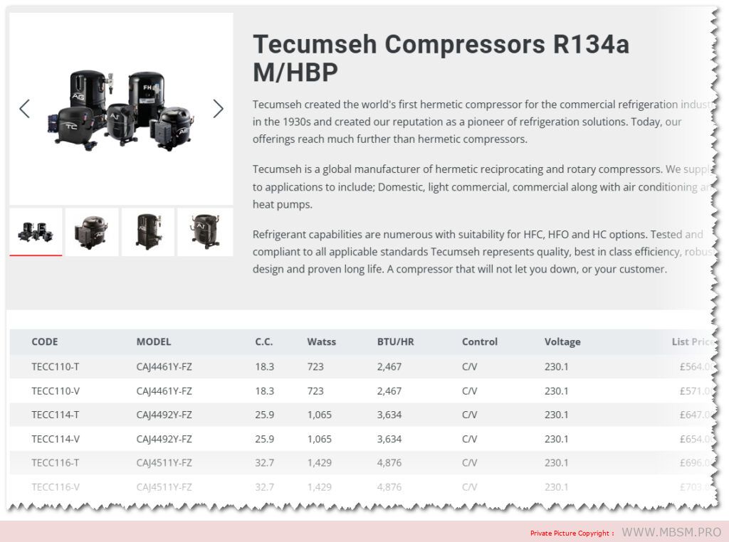
Tecumseh Compressors R134a M/HBP
Tecumseh created the world’s first hermetic compressor for the commercial refrigeration industry in the 1930s and created our reputation as a pioneer of refrigeration solutions. Today, our offerings reach much further than hermetic compressors.
Tecumseh is a global manufacturer of hermetic reciprocating and rotary compressors. We supply to applications to include; Domestic, light commercial, commercial along with air conditioning and heat pumps.
Refrigerant capabilities are numerous with suitability for HFC, HFO and HC options. Tested and compliant to all applicable standards Tecumseh represents quality, best in class efficiency, robust design and proven long life. A compressor that will not let you down, or your customer.
We are professional r134a cmpressor manufacturer. OEM brand production is warmly welcome! 100% products for export Major market Europe,Middle East,South africa,South America We have 80 workers,daily production ability 1X40HQ r134a compressors Just send an inquiry or call us,we’ll let you know the best solution of r134a compressors
Note: This datasheet describes certain operational parameters and conditions for operation of this product. If this product is operated outside of the parameters and conditions stated herein, buyer assumes sole and full responsibility.