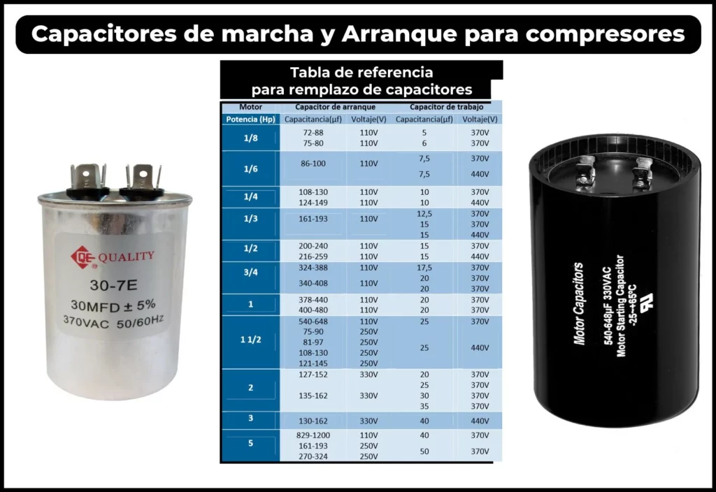
Do you need to replace a start or run capacitor and you don’t know which one the equipment has? In this post we will give you some tables of start and run capacitors so that you can access it when you need it.
The topic regarding the calculation of capacitors for single-phase compressors is of great importance, because whoever is repairing needs to know when it is in poor condition and also what the replacement of the damaged part will be.
The technician who manipulates the equipment has to know that the new capacitor that he has bought to replace the old one must exactly meet the working voltage or greater than that of the original.
It is also important to highlight in this article that the compressor voltage has almost no relation to the capacitor voltage.
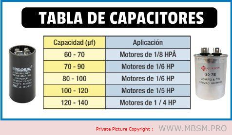
If you do not have the original capacitor data, you can approximate it using the following capacitor values for single-phase motors that we present below.
They can be used as a guide or reference for selecting, replacing capacitors when the exact values are unknown.
Table of starting capacitors for single-phase motors
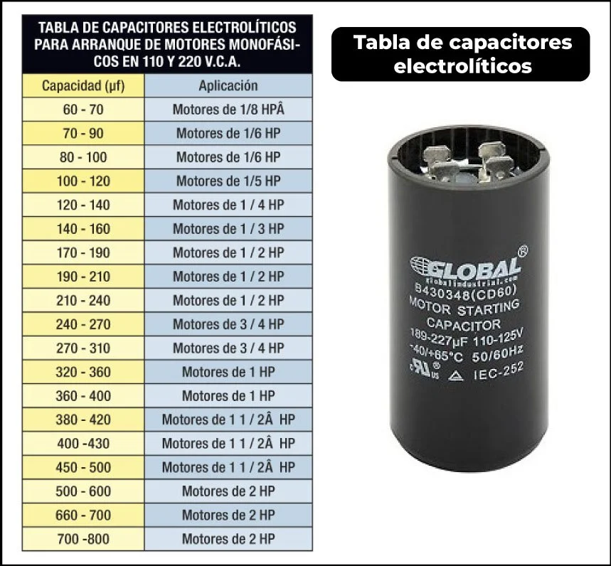
Table of Start and Run Capacitors for Single Phase Capacitors
In this table, which is very similar to the previous one, I attach capacitor values for single-phase motors.
both working and starting capacitors, this way you will have the most user-friendly information in a single image
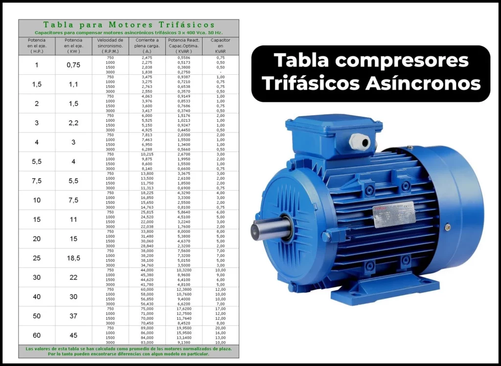
Capacitor Table for Three-Phase Electric Motors
As a general rule, low-power three-phase electric motors have an operating voltage of 220 VD / 380 VY, but we must always make sure .
To do this, it is best to look at the motor’s nameplate. Where the voltages and connection will be indicated to know the type of Capacitor they use.
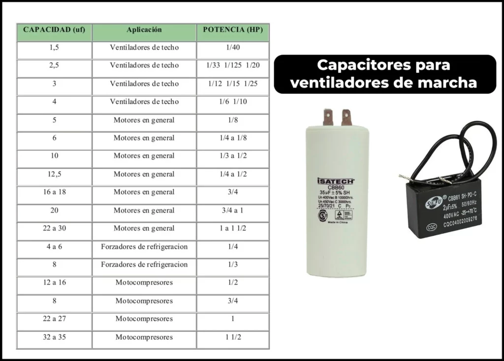
Fan run capacitor table
If you need to change a running or permanent fan capacitor, this table attached below can guide you to resolve the fault of the equipment you are repairing:
Understanding Starting Capacitors for Compressors: A Comprehensive Guide
Introduction Starting capacitors play a crucial role in the efficient operation of compressors, especially in single-phase motors. They help generate the necessary starting torque and ensure smooth operation. This guide provides a detailed overview of starting capacitors, their importance, and how to select the right one for your compressor. We’ll also explore key specifications and troubleshooting tips to ensure optimal performance.
1. What is a Starting Capacitor?
A starting capacitor is an electrical component used in single-phase motors to create a phase shift, which generates the torque needed to start the motor. Without a starting capacitor, single-phase motors would struggle to start due to insufficient torque.
2. Key Functions of Starting Capacitors
Generate Starting Torque: Provides the necessary torque to start the compressor motor.
Phase Shift Creation: Creates a 90-degree phase shift to simulate a second phase in single-phase motors.
Smooth Operation: Ensures the motor starts smoothly without excessive current draw.
3. Table: Starting Capacitor Specifications for Compressors
Compressor Model
Power (W)
Voltage (V)
Capacitance (µF)
Max. Current (A)
Release Current (A)
BSA15
150
230
10
1.55
1.6
BSA10
250
230
15
2.43
2.07
B10A19
300
230
20
3.0
2.56
B12A12
350
230
25
3.5
2.95
B16A13
500
230
30
5.15
4.85
B9A11
750
230
35
7.0
5.9
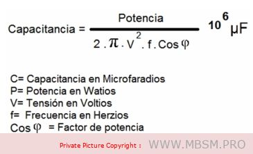
4. How to Calculate the Right Capacitor for Your Compressor
The capacitance of a starting capacitor is critical for optimal performance. Here’s a simple formula to calculate the required capacitance:
Formula:
C=P×1062πfV2cos(ϕ)C=2πfV2cos(ϕ)P×106
Where:
CC = Capacitance (in microfarads, µF)
PP = Motor power (in watts, W)
ff = Frequency (in hertz, Hz, typically 50 or 60 Hz)
VV = Voltage (in volts, V)
cos(ϕ)cos(ϕ) = Power factor (typically 0.85 for motors)
Failed Capacitor: A faulty capacitor can prevent the motor from starting or cause it to overheat.
Incorrect Capacitance: Using a capacitor with the wrong capacitance can lead to insufficient torque or excessive current draw.
Overheating: Poor ventilation or excessive load can cause the capacitor to overheat and fail.
6. Troubleshooting Tips
Check Continuity: Use a multimeter to test the capacitor for continuity. A failed capacitor will show no continuity.
Measure Capacitance: Use a capacitance meter to ensure the capacitor’s value matches the required specifications.
Inspect for Physical Damage: Look for bulging, leaks, or burn marks on the capacitor, which indicate failure.
Test Under Load: Ensure the compressor starts smoothly and does not draw excessive current during startup.
7. Advantages of Using the Right Starting Capacitor
Improved Motor Lifespan: Reduces stress on the motor during startup.
Energy Efficiency: Minimizes power consumption during operation.
Reliable Performance: Ensures consistent and reliable compressor operation.
8. Conclusion
Selecting the right starting capacitor for your compressor is essential for ensuring efficient and reliable operation. By understanding the specifications, calculating the correct capacitance, and performing regular maintenance, you can extend the lifespan of your compressor and avoid costly repairs.
Mbsm.pro, Understanding, Motor, Starting , Systems, for, Compressor
Category: Chaud&Froid
written by www.mbsm.pro | 18 January 2025
Introduction Motor starting systems are critical in ensuring the efficient and safe operation of electric motors across various industries. Choosing the right starting method can significantly impact performance, energy consumption, and equipment longevity. In this post, we’ll explore the most common motor starting systems, their characteristics, advantages, and disadvantages to help you make informed decisions for your applications.
1. Direct-On-Line (DOL) Starting
Characteristics:
Starting current: 5 to 8 times the rated current.
Starting torque: 0.5 to 1.5 times the rated torque.
Direct connection of the stator to the power supply.
Advantages:
Simple and cost-effective.
No additional devices required.
Disadvantages:
High starting current may cause voltage drops in the network.
Not recommended for high-power motors.
2. Star-Delta Starting
Characteristics:
Starting current: 1.5 to 2.6 times the rated current.
Reduced voltage in star mode (3 times lower).
Requires a motor with compatible windings.
Advantages:
Reduces starting current.
Suitable for machines with low resistive torque or no-load starting.
Disadvantages:
Requires a specific motor type.
Not effective for heavy loads.
3. Part-Winding Starting
Characteristics:
Starting current: Approximately half of DOL starting.
Starting torque: Higher than star-delta.
Uses two parallel windings.
Advantages:
Lower starting current.
Higher starting torque compared to star-delta.
Disadvantages:
Rarely used in Europe.
Requires a motor with specific windings.
4. Stator Resistance Starting
Characteristics:
Starting current: 4.5 times the rated current.
Starting torque: 0.75 times the rated torque.
Resistors in series with the windings.
Advantages:
Reduces starting current.
No winding modification required.
Disadvantages:
Energy losses in resistors.
Requires a timer to remove resistors.
5. Autotransformer Starting
Characteristics:
Reduced voltage during starting.
Three stages: star, partial coupling, and full voltage.
Selectable transformation ratio.
Advantages:
Reduces starting current.
Flexible voltage selection.
Disadvantages:
Expensive and complex.
Requires additional space for the autotransformer.
6. Electronic Soft Starter
Characteristics:
Limits current and adjusts torque.
Smooth start and stop.
Electronic control of applied voltage.
Advantages:
Smooth starting reduces mechanical stress.
Energy savings.
Disadvantages:
Higher initial cost.
Requires maintenance of the electronic system.
7. Variable Frequency Drive (VFD) Starting
Characteristics:
Speed and torque control.
Suitable for high-inertia loads.
Optimizes energy consumption.
Advantages:
Precise speed control.
Ideal for applications requiring variable speed.
Disadvantages:
High initial cost.
Requires technical expertise for setup and maintenance.
Conclusion
Selecting the right motor starting system depends on factors such as motor size, load type, and operational requirements. While DOL starting is simple and cost-effective, more advanced systems like soft starters and VFDs offer greater control and efficiency, albeit at a higher cost. Understanding these systems will help you optimize performance, reduce energy consumption, and extend the lifespan of your equipment.
If you have any questions or need further assistance in choosing the right motor starting system for your application, feel free to leave a comment or contact us!
Tags: Motor Starting Systems, Electric Motors, Soft Starters, VFD, Star-Delta Starting, Industrial Automation Categories: Electrical Engineering, Industrial Automation, Energy Efficiency
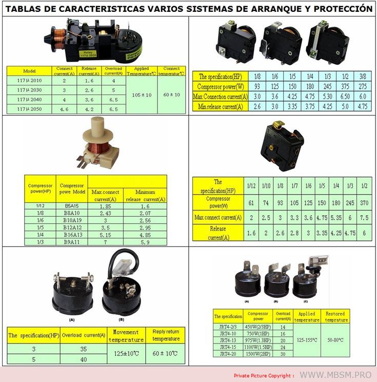
table organizes the information for better readability and understanding:
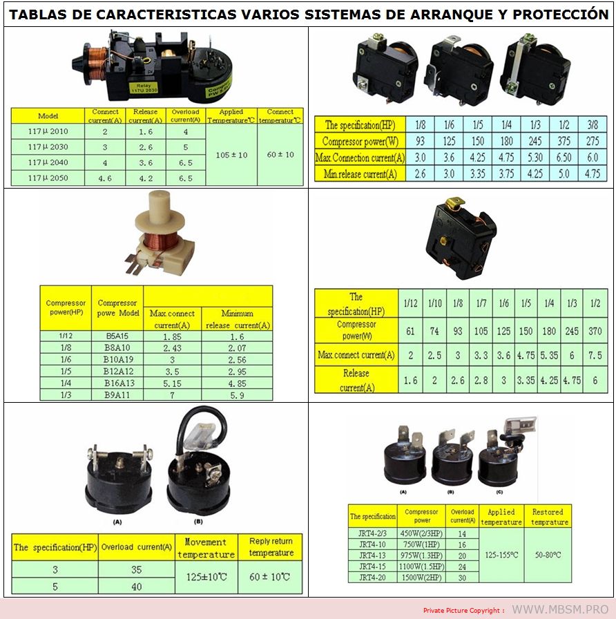
Content Table: Motor Starting Systems and Protection Specifications
1. General Specifications
Model
Concesor Current (A)
Relaxo Current (A)
Overload Current (A)
Applied Temperature (°C)
Concesor Temperature (°C)
1171/2010
2
1.6
4
–
–
1171/2030
3
2.6
5
105 ± 10
60 ± 10
1171/2040
4
3.6
6.5
–
–
1171/2050
4.6
4.2
6.5
–
–
2. Compressor Power Specifications (HF)
Component Power (HF)
Compressor Power Model
Max. Connection Current (A)
Minimum Release Current (A)
1/12
BSA15
1.55
1.6
1/8
BSA10
2.43
2.07
1/6
B10A19
3
2.56
1/5
B12A12
3.5
2.95
1/4
B16A13
5.15
4.85
1/3
B9A11
7
5.9
3. Compressor Power and Current Ratings
Component Power (HF)
Compressor Power (W)
Max. Connection Current (A)
Release Current (A)
1/12
61
2
1.6
1/10
74
2.5
2
1/8
93
3
2.6
1/7
105
3.3
2.8
1/6
125
3.6
3
1/5
150
4.75
3.35
1/4
180
5.35
4.25
1/3
245
6
4.75
1/2
370
7.5
6
4. IRFA Series Specifications
Model
Compressor Power (W)
Max. Connection Current (A)
Release Current (A)
IRFA-20
450W (20HF)
14
–
IRFA-10
750W (1HF)
16
–
IRFA-13
975W (1HF)
20
–
IRFA-15
1100W (2HF)
24
–
IRFA-20
1500W (2HF)
30
–
5. Additional Notes
Concesor Current: The current drawn by the compressor during operation.
Relaxo Current: The current at which the system releases or disconnects.
Overload Current: The maximum current the system can handle before tripping.
Applied Temperature: The operating temperature range for the system.
Concesor Temperature: The temperature range for the compressor during operation.
This table provides a clear and organized overview of the motor starting and protection systems, including their specifications and performance metrics. Let me know if you need further assistance!
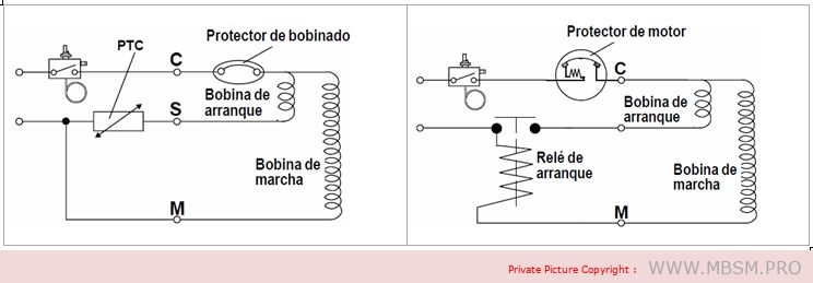
Sistemas de arranque:
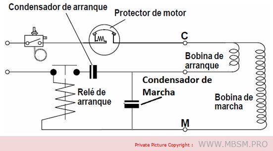
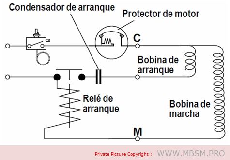
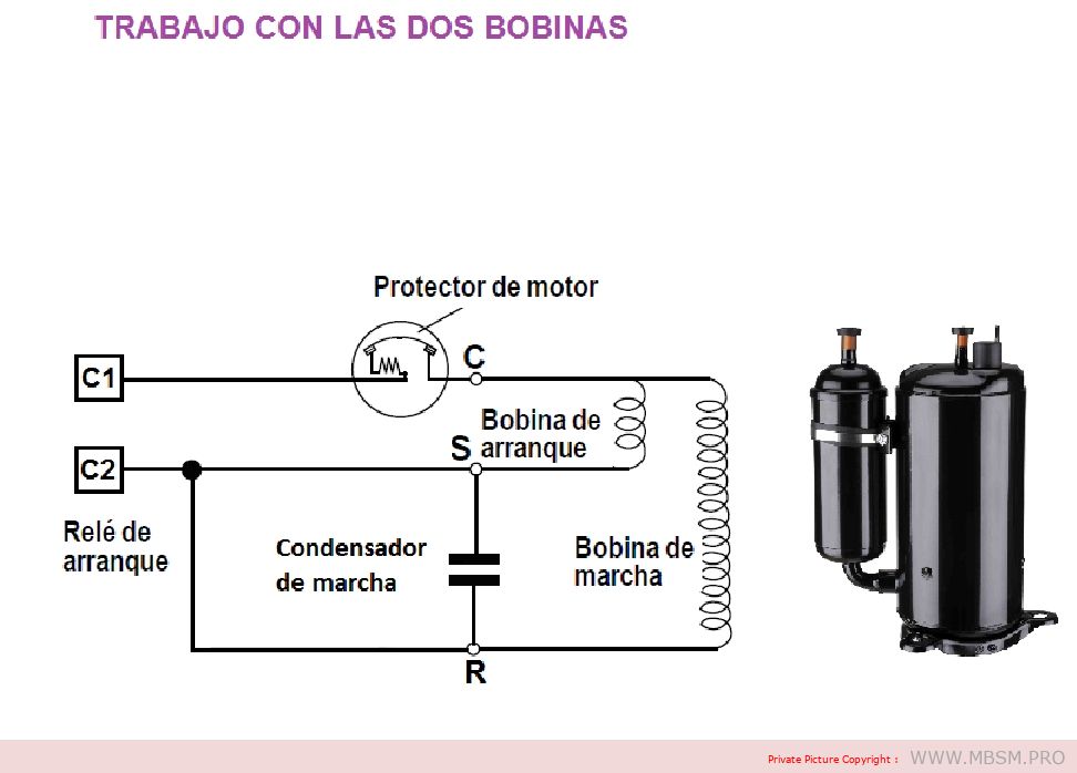
En el caso del relé de arranque, cuando la energía es aplicada al compresor, la bobina solenoide del relé atrae la armadura del mismo para arriba produciendo el cierre de los contactos, energizando la bobina de arranque del motor. Cuando el motor del compresor alcanza la velocidad de funcionamiento, la corriente de la bobina principal del motor será tal que la bobina solenoide del relé desenergiza permitiendo que los contactos del relé se abran, desconectando de esta manera la bobina de arranque del motor.
The PTC is a semiconductor with a positive temperature coefficient, which means that it offers no resistance to the passage of current when the unit is cold. When the unit is turned on, the current passing through the PTC causes it to heat up rapidly, creating such a high resistance in its circuit that the passage of current remains at a very low value but high enough to keep the PTC warm.
Prerequisites for using the PTC system:
– The thermostat must be used to ensure that the stop time allows for pressure equalisation in the system. – Depending on the size of the compressor, the stop period should be at least 3 to 5 minutes (e.g. the minimum times for TL are 3 minutes, and for SC 5 minutes).
The PTC system offers a number of advantages:
– Improved protection of the starter coil – PTC is not affected by voltage increases or decreases – Free from radio and television interference – No wear – Identical PTC starter system for many compressors of different sizes.
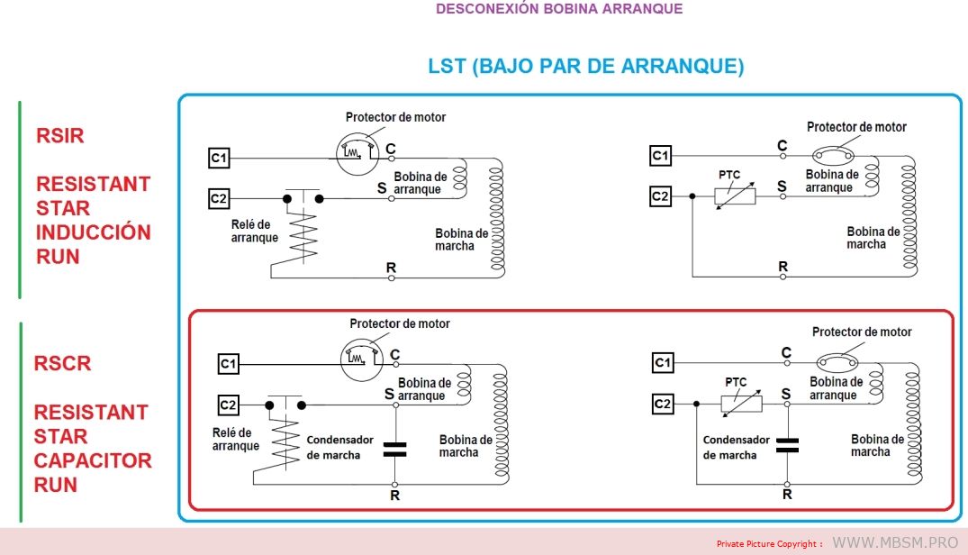
LST (low starting torque) engines
Compressors with RSIR and RSCR system motors have a low starting torque (LST) and are used in refrigeration appliances with capillary tubes, where pressure equalization takes place before each start.
The RSIR system incorporates a PTC thermistor or a relay and a bifilar winding (current relay) as starting equipment. The PTC needs to be kept off for a period of about 5 minutes to allow it to cool down before it can restart.
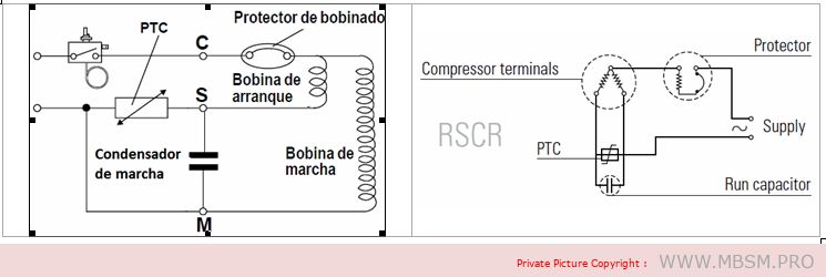
RSCR (Resistant Start Capacitor Run): Induction motor with resistor start and run capacitor.
The RSCR system, consisting of a PTC thermistor and a run capacitor, is mainly used in energy-optimized compressors.
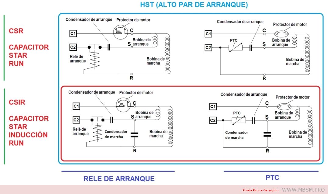
HST (High Starting Torque) Engines
Compressors with CSIR and CSR type motors have a high starting torque (HST) and can be used in refrigeration appliances with capillary tubes as well as in systems with expansion valve operation (without pressure equalization).
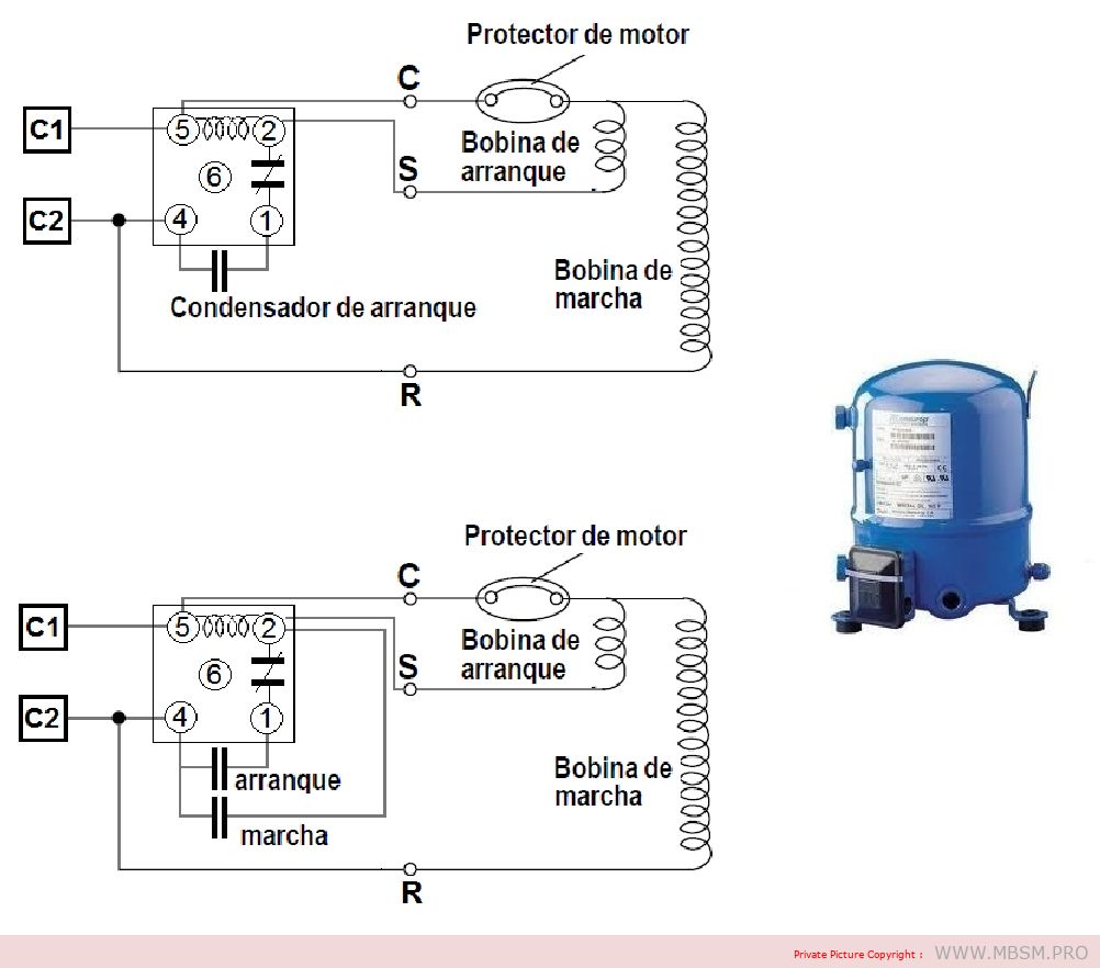
– CSR (Capacitor Start Run): Induction motor with start capacitor and run capacitor
CRS systems require a voltage relay, a start capacitor and a run capacitor.
– CSIR (Capacitor Start Induction Run): Induction motor with starting capacitor.
The CSIR system consists of the starting relay and starting capacitor specified for each particular compressor type.
Graphic summary:
Conditions for a long service life
To achieve trouble-free operation and long service life of the hermetic compressor, the following conditions must be met:
1. The starting torque must be sufficient to enable the motor to start under the prevailing pressure conditions in the system. 2. The maximum torque of the motor must be sufficient to enable the motor to withstand the load conditions at start-up and during running. 3. During operation of the refrigeration system, the temperature of the compressor must never rise to levels that could damage its components. Condensation and compression temperatures must therefore be kept as low as possible. 4. Correct sizing of the refrigeration system in question, and a correct assessment of the operating conditions of the compressor under maximum loads. 5. Sufficient cleanliness and minimum residual moisture in the system.
Engine overload
The motor start-up is determined by the starting torque and/or the maximum torque of the motor. If the starting torque or the maximum torque are insufficient, the compressor cannot start or the start-up will be hindered and delayed due to the activation of the internal motor protector.
Repeated starting attempts subject the motor to overload, which will sooner or later result in failure. It is all a matter of selecting the right compressor for extreme working conditions.
Thermal overload
To ensure a long compressor life, operating conditions that lead to thermal decomposition of the materials used in the compressor must be avoided. The materials involved are coolant, oil and materials for motor insulation. Motor insulation consists of enamel for the copper winding, insulation for the stator core slot, insulating tape and power cables.
The R 134a, R 404A or R 507 refrigerants used today require advanced oils. Only special quality POE oils (polyester) are used.
For the application of compressors in domestic and commercial refrigeration devices with the refrigerants that are currently available, it is advisable to comply with the following rules.
Coil temperature
The coil temperature must never exceed 125°C during continuous operation. For limited periods of time, e.g. during compressor start-up or in case of short load peaks, the temperature should not exceed 135°C.
For commercial refrigeration with R 134a, the same values apply as for domestic refrigeration. However, cooling the compressor by means of a fan is recommended.
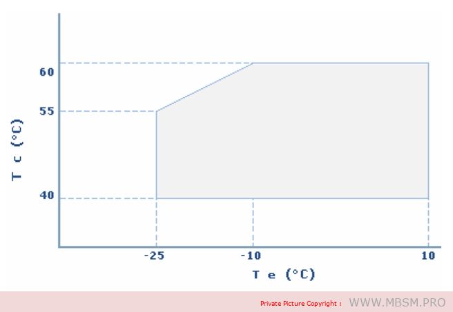
Condensation temperature
When using R 600a or R 134a refrigerants, the condensation temperature during continuous operation must not exceed 60°C. During short load peaks, the temperature must not exceed 70°C.
In commercial refrigeration where R 404A and R 507 refrigerants are used, the condensation temperature limit is 48°C during continuous operation and 58°C during peak loads.
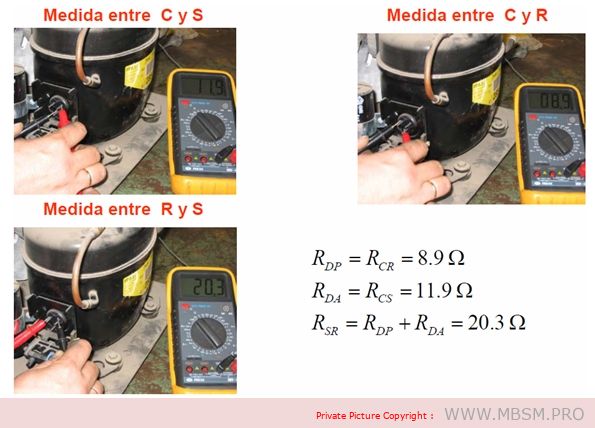
Checking the compressor coils.
We must take into account that we are going to check an electromechanical part since it has an electrical part that makes another mechanical part work and it is necessary to carry out several types of tests to be able to determine if it is damaged and if it is possible to find out which part of the compressor is damaged. For these tests we will need measuring tools and a little expertise since in some we will use the senses, we will divide the tests into two parts, one when it is installed and the other when the compressor is alone without being installed.
Measure continuity between the compressor coils:
For this test we will need a tester that measures continuity, we will have to disconnect the compressor cables, the test consists of verifying that there is continuity between the compressor terminals and measuring two by two we verify if there is no continuity in these terminals, we must take into account the temperature of the compressor, if it is cold the coil is open (damaged), if the compressor is hot we must wait for it to cool down because it may be that the thermal switch is open due to high temperature and we perform the test again.
If you are disconnected or off the computer, this test is performed in the same way.
Test if the amperage is too high:
For this test we will need a clamp meter and we will place it in one of the compressor lines, either the common one, preferably the start (maintenance) line, it should not be placed on the start-up line because it will not give us the measurement we need to check, we must know the normal working amperage of the compressor, start it, wait for it to stabilize, at start-up it normally consumes 5 times the working amperage, we wait for it to stabilize and if it is above that indicated on the plate it is too high in amperage, in this case we will have to check, capacitor, ventilation, pressures, voltage tension, to determine if it is because of the compressor or an external cause. If the compressor is disconnected from the equipment and the amperage exceeds that indicated it is a sign that it is damaged and we should not install it.
Determine if compressor pumps well:
Pressure test: it is not advisable to measure the output pressure, however there are technicians who when buying a used compressor usually measure the high pressure, if it exceeds 300 psi the compressor is fine and if when turning it off the pressure is maintained without it returning, it is an excellent sign that everything is fine, it is not low on compression since the valves do not return pressure, this test is not performed on rotary compressors because they work with the pressure and temperature of the same compressor to reach the normal working refrigerant gas pressure.
If the compressor is installed when measuring with the pressure gauge and registering that the high pressure does not rise and the low pressure is very high, it is a sign of decompression. If it is a rotary equipment, we look at the suction filter that is located at the compressor inlet to see if it freezes. If it is frozen it is due to obstruction. If, upon observing this, everything is normal, it is most likely that the pressures are destabilized due to low compression. Another sign is that the amperage with the low pressure high and the high pressure low will show a consumption well below normal since it is not exerting force to maintain a high pressure in the condenser.
Determine if the compressor is seized:
For this we need to use the ammeter or clamp meter when trying to start the having a suitable capacitor and in good condition it should not exceed the starting amperage which is 5 times the nominal or working amperage, if it exceeds it is a sign that it is blocked, we can use an additional starting aid to the capacitor and if with this the result is the same (taking into account that the voltage is normal) we will determine that the compressor is seized and it is necessary to replace it.
When I mention at the beginning that we should use our senses, I mean that if we are testing a compressor and we notice a strange noise when starting it, this is not a good sign, and if it is already in full operation and sounds unusual, it is a bad sign, as well as looking at the part where the cables are connected to the compressor, since this is a seal that sometimes gets damaged and allows oil to leak, be attentive and verify that the filter that is fixed by a belt in the case of rotary compressors is not subject to this belt being damaged, since it also produces noise, refrigerant gas leaks and vibrations, these are details that we should be very attentive to.
Note: We should always try to exhaust every last resource to determine if a compressor is damaged, because if we are technicians and they seek a second opinion, and it works in the hands of the second opinion, the client will think the worst of us and our reputation will be in jeopardy, and if the compressor is our property, we should also exhaust all resources, since it is the most expensive part of our air conditioning, both its individual price and the expenses generated in labor and materials for its installation. We must be very clear that it no longer works for ourselves and for others.
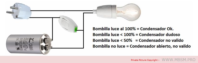
Checking the starting capacitor.
To test a starting capacitor in a simple way, we simply connect it in series with an incandescent light bulb and supply it with AC voltage. We will also complement the assembly with a normally open push button like the one used in doorbells, which we will connect in parallel with the capacitor according to the following diagram.
Calculation of the starting capacitor capacity:
Many refrigeration compressors are single-phase motors. The problem with supplying a motor with 230 V, with a single phase, means that the torque needed for starting is not generated. To “trick” the motor and generate a fictitious phase, a capacitor is used that shifts the supply voltage by 90º. In this way, we will have the necessary starting torque. To obtain the best and most powerful starting torque of the single-phase motor, which will result in the refrigeration compressor working better and with more force and not jamming… the capacity of the capacitor that obtains this 90º phase shift must be calculated.
It is not true that the larger the capacitor, the greater the starting torque of the single-phase motor. The only thing that is obtained is a greater phase shift, which will produce a lower starting torque of the single-phase motor. In fact, if the capacitor is too large, it may happen that the phase shift is 360º, that is, 0º, so that the single-phase motor would have no starting torque. In any case, capacitors with a higher or lower capacity than necessary will generate phase shifts lower or higher than the optimum, which will result in starting torque values lower than the optimum. Starting with starting torque lower than the optimum can result in our single-phase motor burning out; it has to make more effort than necessary to start, the intensity increases and the motor burns out, which would end up being damaged.
The highest starting torque for the single-phase motor is obtained when the phase shift we obtain with our capacitor is 90º. To obtain this phase shift we will proceed to calculate the capacitor of a single-phase motor in the following way.
Suppose we have an engine with the following characteristics
Power 150 W Working voltage 230 V. Frequency 50 Hz. Cosine of phi = 0.85
Applying the formula, the capacitance is 10.61 microfarads.
Therefore, the optimal ideal capacitor for the single-phase motor in the example is 10.61 uF, as 10.61 micro Farads is a capacitor value that we cannot find on the market, we will choose to buy the value that is closest in this case 10 micro Farads.
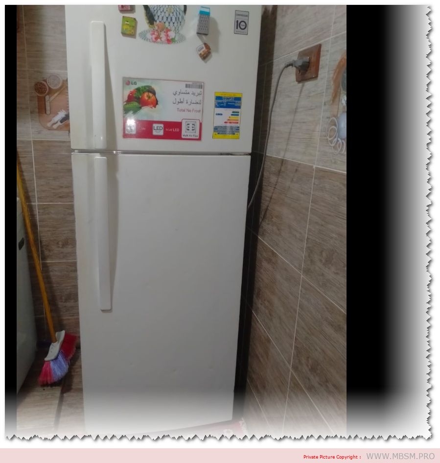
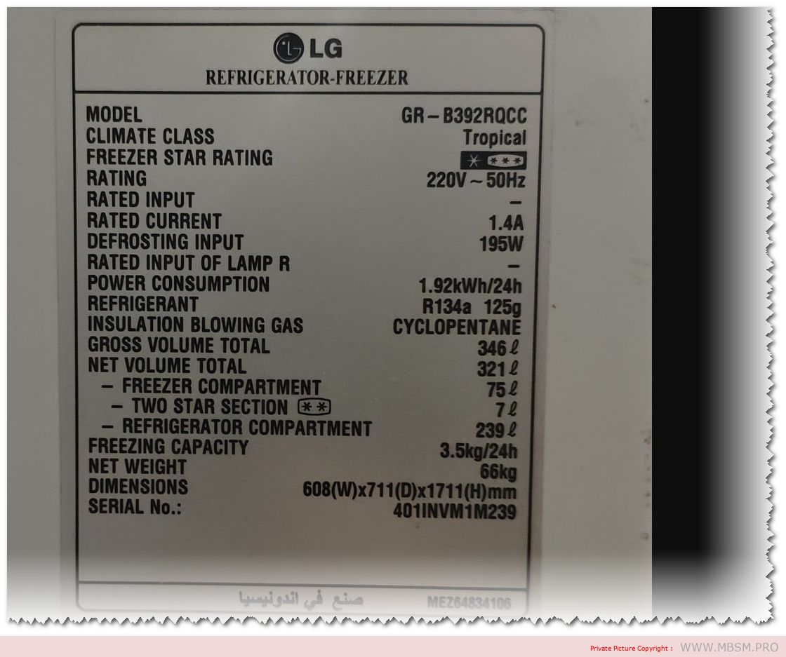
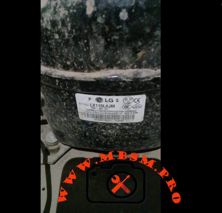
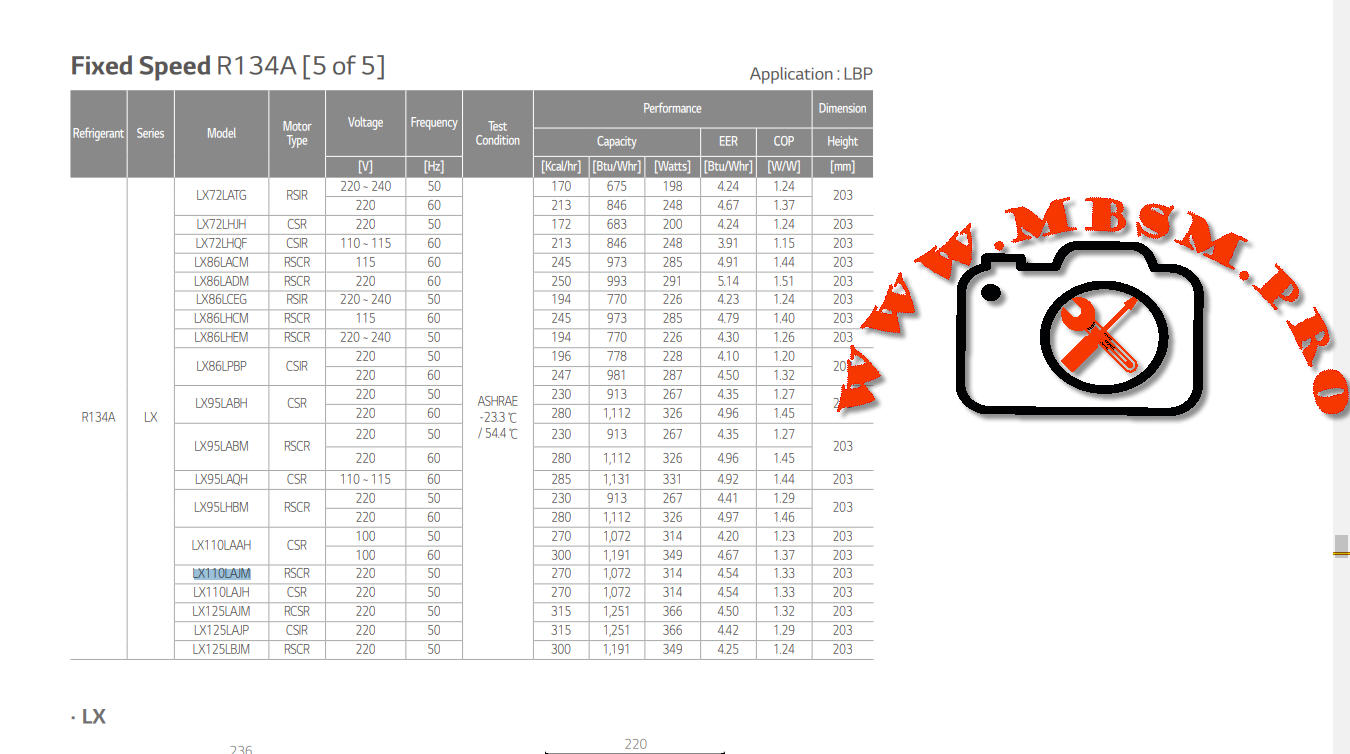
The LG GR-B392RQCC is a refrigerator-freezer model with the following specifications:
Specification
Details
Model
GR-B392RQCC
Total Gross Volume
364L
Compressor Type
Smart Inverter Compressor
Compressor Power
1/5 hp
Refrigerant
R134a (125g)
Rated Current
1.4 A
Power Supply
1 Phase, 220V
This model features a smart inverter compressor, which enhances energy efficiency and cooling performance. The total gross volume of 364 liters provides ample space for food storage
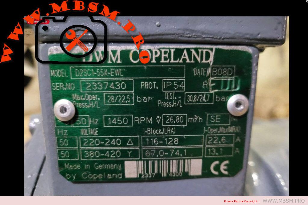
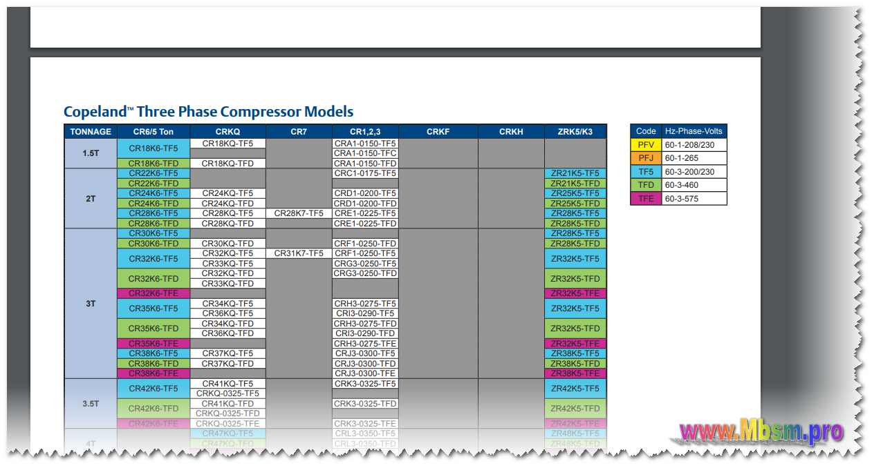
Copeland compressor can be used for low/medium and high temperature. These compressors are from Copeland China factory.
DWM Copeland™ Compressors are suitable For a wide range of applications either in the form of single compressors, condensing units or as multi-compressor equipment
Cooling Capacity at Standard Condition 2.67kWR404A, Evaporating -35° C, Condensing 40° C, Suction Gas Return 20° C, Sub cooling 0K
Mechanical Data Number of cylinders2.0Displacement @ 50 Hz, cu. M/h18.2 Bore/Stroke, mm60.4/36.5Length/Width, mm470/330 Height, mm385.0Net Weight, kg87.0 Gross Weight, kg93.0Suction, inch1 1/8 Discharge, inch5/8Oil Quantity, l2.0 Frequency Range, Hz25 – 60Base mounting (hole dia), mm295 x 279 (14.0) Sound Pressure @ 1m, dBA63.1Sound Power, dBA74.1 High Side PS, bar(g)28.0Low Side PS, bar(g)22.5 Electrical Data Maximum Operating Current, A9.5Locked Rotor Current, A68.5 Default Enclosure ClassIP 54 (IEC 34) Accessories Mounting Springs4 Additional Cooling1 or 2 ways water Coil Crankcase Heater70W Internal Additional Cooling70W Vertical Air Flow Fan Additional Cooling25W Horizontal Air Flow Fan Adapter KitFor Parallel Operation InverterControl Techniques SKB 3400750
Model:SC21G Refrigerant:R134A Power:220-240V/50/60HZ Back Pressure:Low/High Power Source: AC Power
Description
We take ‘Quality Standards, Innovation, Continuous Improvement, Customer Satisfaction’ as our quality policy, take the recruitment of talents as the foundation of the enterprise, and regard improving product quality as our mission. We provide you with a one-stop service for Tecumseh Piston Compressor For Air Conditioning, 30HP Copeland Semi-hermetic Compressor, DIXELL Controller For Compressor at a reasonable price. Welcome domestic and foreign customers to call and negotiate. We also continuously innovated and improved our enterprise management system to improve efficiency, providing professional, reliable and high-quality products to serve customers around the world. If you pursuit the Hi-quality, Hi-stable, Competitive price parts, company name is your best choice! We are dedicated to the satisfaction of customers and try to meet their different requirements, sample orders are accepted.
Hot sales R134a SECOP Piston Compressors SC21G
Product introduction
SECOP Hermetic Piston Compressors
Model:SC21G
Refrigerant:R134A
Power:220-240V/50/60HZ
Back Pressure:Low/High
Power Source: AC Power
Voltage range[V]:187- 254
Evaporating temperature [F]:-25 to -5
Transport Package: Wood Package
Product feature
Model
Electric Source
Power(HP)
Capacity(W)
Refrigerant
Back Pressure
SC15CM
220V-240V 50Hz
1/2HP
375
R22
Low
SC18CM
220V-240V 50Hz
5/8HP
469
R22
Low
SC15D
220V-240V 50Hz
5/8HP
469
R22
High
SC15G
220V-240V 50Hz
3/8HP
281
R134a
Low/High
SC18G
220V-240V 50Hz
1/2HP
375
R134a
Low/High
SC21G
220V-240V 50Hz
5/8HP
469
R134a
Low/High
SC10CL
220V-240V 50Hz
1/3HP
250
R404A
Low
SC15CL
220V-240V 50Hz
1/2HP
375
R404A
Low
TL5G
220V-240V 50Hz
R134A
Low/High
Product Application
Cold storage, frozen food processing and storage, quick freezing cold storage, low temperature shelf, ice cream machine, showcase, chiller, large integrated air conditioning, laboratory and medical equipment, cold dryer, glass door commercial freezer, vending machine, Ice machine, beverage cabinet, heat pump, milk cooling tank, etc.
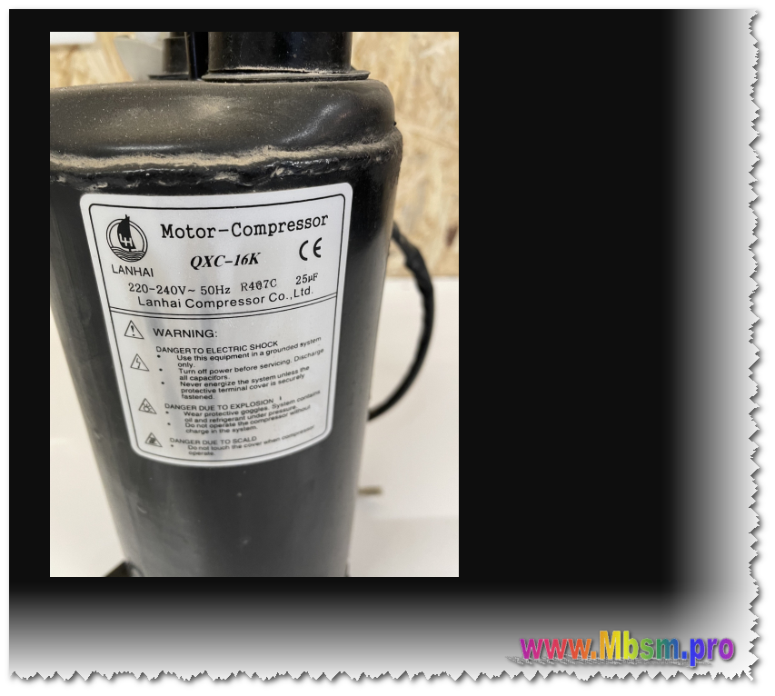
The QXC-16K is a rotary compressor designed for refrigeration applications, particularly in dehumidifiers and air conditioning systems. Here are its key specifications and features:
Specifications
Model: QXC-16K
Refrigerant Type: R407C
Voltage: 220-240V, 50Hz
Cooling Capacity: 2670 W (approximately 9078 Btu/h) at an evaporating temperature of +7.2°C and condensing temperature of +54.4°C.
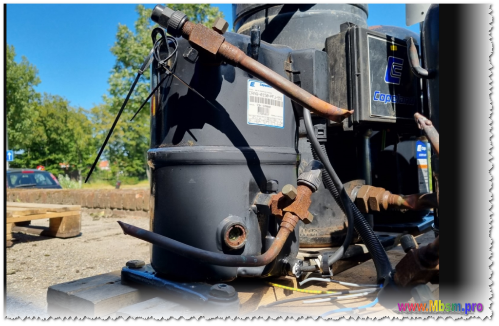
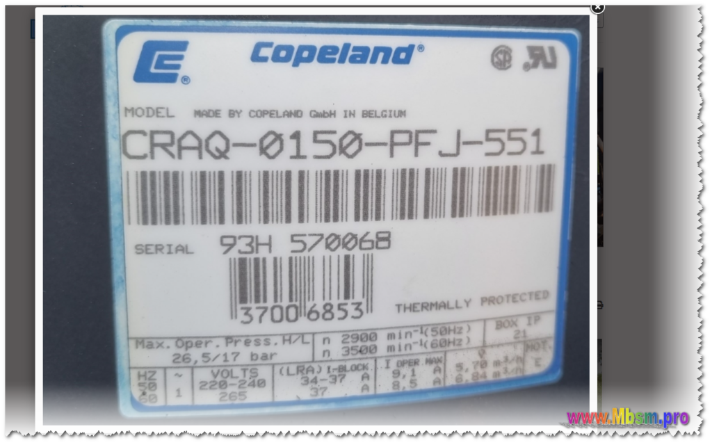
The compressor model CRAQ-0150-PFV-501 is a Hermetic compressor manufactured by Copeland. It is a 1-phase, 208/230V compressor designed for air conditioning applications. The compressor uses HCFC or R-22 refrigerant and operates at 60Hz.
Here are some of the key specifications of the CRAQ-0150-PFV-501 compressor:
Capacity: 18,300 – 23,900 BTU/hr
Power: 1,910 – 1,520 W
Current: 8.8 – 7.0 Amps
EER: 9.6 – 15.7 BTU/Wh
Mass Flow: 268 – 308 lbs/hr
Sound Power: 72 – 77 dBA
Vibration: 1.7 – 2.7 mils (peak-peak)
Displacement: 2.00 in^3/Rev
Overall Length: 9.44 in
Overall Width: 9.13 in
Overall Height: 13.56 in
Mounting Length: 7.50 in
Mounting Width: 7.50 in
Mounting Height: 13.94 in
Suction Size: 5/8 in
Discharge Size: 3/8 in
Initial Oil Charge: 55 oz
Oil Recharge: 51 oz
Net Weight: 61.0 lbs
Internal Free Volume: 345.0 in^3
This compressor is no longer in production and has been replaced by newer, more efficient models. However, it is still a popular choice for replacement applications due to its reliability and performance.