Unionaire PUQ012HR5R0WPK 12000 BTU Heat Pump Compressor Technical Specifications and R22 System Overview
Focus keyphrase: Unionaire PUQ012HR5R0WPK 12000 BTU Heat Pump Compressor Technical Specifications and R22 System Overview
SEO Title: Mbsmpro.com, Unionaire, PUQ012HR5R0WPK, 12000 BTU, Heat Pump, R22, 1.2 HP, 220-240V, Rotary Compressor Specs
Meta Description: Technical deep dive into the Unionaire PUQ012HR5R0WPK outdoor unit. Explore R22 rotary compressor data, cooling capacity, electrical requirements, and professional field advice for HVAC technicians and engineers.
Slug: unionaire-puq012hr5r0wpk-12000btu-heat-pump-r22-specs
Tags: Unionaire, PUQ012HR5R0WPK, 12000 BTU, R22, Heat Pump, Rotary Compressor, HVAC, Mbsmgroup, Mbsm.pro, mbsmpro.com, mbsm, PH215X2C-4FT1, PA145X2C-4FT, ASD102RK, 2K22S225, BSA645RV
Excerpt: The Unionaire PUQ012HR5R0WPK is a robust 12,000 BTU reversible heat pump system designed for demanding climates. Utilizing an R22 rotary compressor, this unit balances efficiency and reliability. Our technical breakdown covers electrical parameters, pressure ratings, and compatible replacements, providing field workers with the essential data needed for professional maintenance, system repairs, and component sourcing.
Professional Engineering Review: Unionaire PUQ012HR5R0WPK 1.5 HP Heat Pump System
In the world of residential and light commercial HVAC, the Unionaire PUQ012HR5R0WPK stands as a testament to the era of high-reliability R22 systems. Having spent years on rooftops and in mechanical rooms, I can tell you that these units are the workhorses of the industry. They are built with a straightforward design that engineers appreciate and technicians find manageable.
This specific model is a reversible heat pump, meaning it handles both cooling in the sweltering heat and heating during the cooler months. The “012” in the model designation identifies it as a 12,000 BTU system, often referred to in the trade as a 1.5 HP unit.
Technical Core Specifications
| Feature | Data Detail |
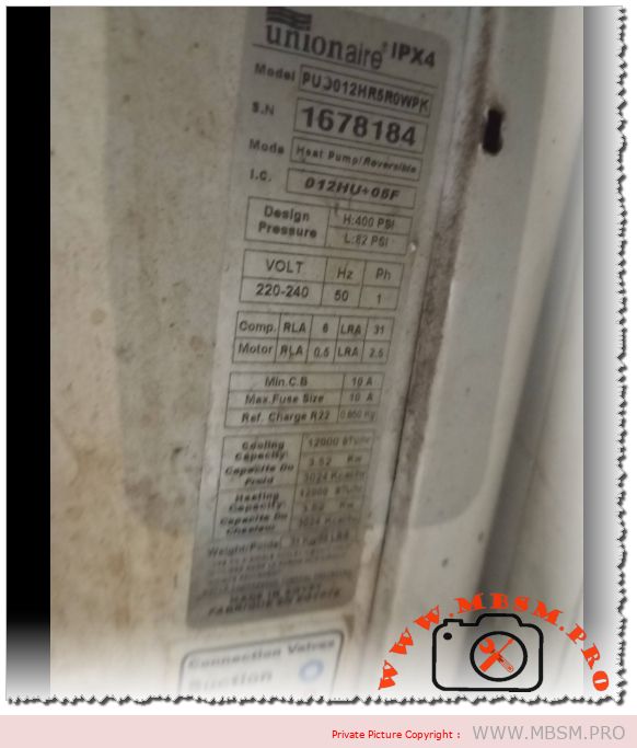
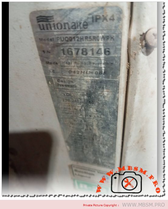
| Model | PUQ012HR5R0WPK |
| System Type | Heat Pump (Reversible) |
| I.C. Code | 012HLH05F |
| Cooling Capacity | 12,000 BTU/h |
| Power Supply | 220-240V / 50Hz / 1 Phase |
| Design Pressure (High) | 400 PSI |
| Design Pressure (Low) | 82 PSI |
| Protection Rating | IPX4 (Splash-proof) |
Compressor Performance and Efficiency Metrics
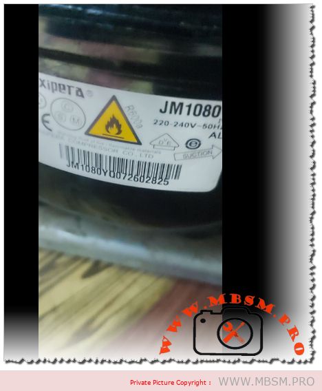
For the engineer looking at performance curves, the rotary compressor inside this unit is optimized for Air Conditioning (HBP) but can be analyzed across various evaporating temperatures to understand its efficiency limits.
Efficiency Metrics (COP) and Cooling Capacity
| Evaporating Temp (°C) | Cooling Capacity (Watts) | Power Consumption (Watts) | COP (W/W) |
| -15 | 1150 | 680 | 1.69 |
| -10 | 1580 | 740 | 2.14 |
| -5 | 2100 | 810 | 2.59 |
| 0 | 2750 | 890 | 3.09 |
| +4.4 (Standard) | 3517 | 1050 | 3.35 |
| +7.2 | 3850 | 1120 | 3.44 |
| +10 | 4200 | 1180 | 3.56 |
Comprehensive Technical Data Table
| Parameter | Specification Details |
| Utilisation | HBP (High Back Pressure) |
| Domaine | Cooling / Heating (Reversible) |
| Cooling wattage at -23°C | Not applicable (HBP design ~ 650W estimated) |
| Cubic feet system can cool | 1,500 – 2,000 cu. ft. (Approx. 20m²) |
| Litres system can cool | N/A (Standard AC Application) |
| Kcal/h | 3,024 Kcal/h |
| Oil Type and Quantity | Mineral Oil (MO) / 350ml |
| Horsepower (HP) | 1.2 HP (Compressor) / 1.5 HP (System) |
| Refrigerant Type | R22 |
| Motor Type | PSC (Permanent Split Capacitor) |
| Displacement | 15.0 cc to 16.4 cc |
| Winding Material | Copper |
| Pression Charge | High: 250-300 PSI / Low: 60-70 PSI (Typical) |
| Capillary Size | 0.050″ or 0.054″ ID |
| Amperage (FLA) | 5.2 A – 6.0 A |
| LRA (Locked Rotor Amps) | 28 A – 32 A |
| Type of Relay | Not required (PSC Motor) |
| Capacitor Value | 30µF or 35µF / 450V |
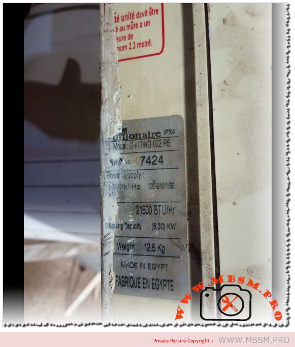
| Country of Origin | Egypt / International Export |
System Comparison: R22 vs. Modern Alternatives
When comparing this Unionaire unit to modern R410A or R32 systems, several field nuances emerge:
- Pressure Management: The 400 PSI high-side design of this R22 unit is significantly lower than R410A systems, which often exceed 550 PSI. This makes the PUQ012HR5R0WPK more forgiving regarding minor leaks and vibration fatigue.
- Maintenance: Being an R22 system, mineral oil is used. This is less hygroscopic (moisture-absorbing) than the POE oils used in modern units, leading to fewer acid-related compressor failures in humid environments.
Technical Wiring Diagram Overview (Heat Pump)
For technicians troubleshooting the electrical side, here is the standard logic for this reversible system:
- Terminal C (Common): Connected to the Neutral/L2.
- Terminal R (Run): Connected to Live/L1.
- Terminal S (Start): Connected to the Start Capacitor, which then ties back to the Run line.
- Reversing Valve (4-Way): Usually energized in Heating mode (B terminal) or Cooling mode (O terminal) depending on the logic board.
- Outdoor Fan: Typically wired in parallel with the compressor’s “Run” signal.
Professional Tips and Field Maintenance Notes
- Coil Cleaning: Because this unit is rated IPX4, it handles outdoor exposure well, but the aluminum fins are prone to oxidation. Use a non-acidic coil cleaner to preserve the heat exchange rate.
- Vibration Check: Ensure the compressor mounting grommets are supple. Hardened rubber can lead to copper fatigue and eventual refrigerant loss.
- Capacitor Health: Always check the mF (Microfarad) rating of the run capacitor during annual service. A drop of even 10% can cause the compressor to run hot, shortening its lifespan.
Cross-Reference Replacement Guide
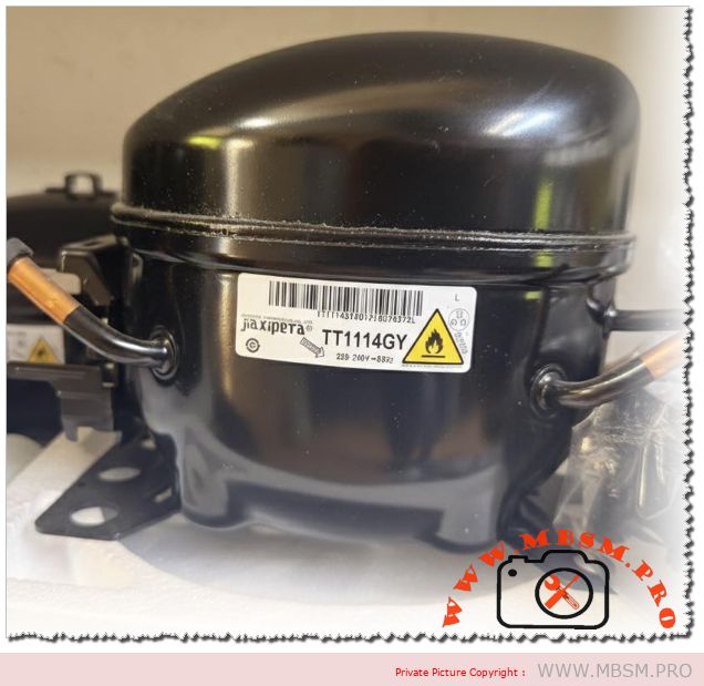
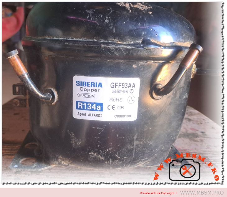
If the original compressor fails, these are the top-tier professional choices for replacement.
5 Compressor Replacements (Same Gas: R22)
| Brand | Model | Capacity | Notes |
| GMCC | PH215X2C-4FT1 | 12,000 BTU | Direct fit, high reliability |
| Highly | ASD102RK | 12,200 BTU | Excellent energy rating |
| Panasonic | 2K22S225 | 12,100 BTU | Quiet operation |
| Hitachi | BSA645RV | 11,950 BTU | Compact footprint |
| Toshiba | PA145X2C | 12,000 BTU | Rugged design |
5 Compressor Replacements (Alternative Gas: R410A)
Note: Requires full system flush, expansion valve change, and POE oil.
| Brand | Model | Capacity | Displacement |
| GMCC | PA125X2C | 12,000 BTU | 12.5 cc |
| Highly | ASA102RK | 12,300 BTU | 10.2 cc |
| LG | QJS124P | 12,000 BTU | High efficiency |
| Rechi | 44R282A | 11,800 BTU | Standard replacement |
| Mitsubishi | RN110 | 12,000 BTU | Premium choice |
Final Engineering Analysis
The Unionaire PUQ012HR5R0WPK remains a vital component in many existing installations. Its 82 PSI low-side design point indicates a system built for stability. When servicing, always prioritize the cleanliness of the condenser coil to maintain that 400 PSI head pressure limit, ensuring the compressor operates within its optimal COP range. Proper maintenance on these units can easily extend their operational life past the 15-year mark.