Samsung front‑load tub front half assembly: dimensions, components and replacement guide

Samsung front‑load tub front half assembly: dimensions, components and replacement guide

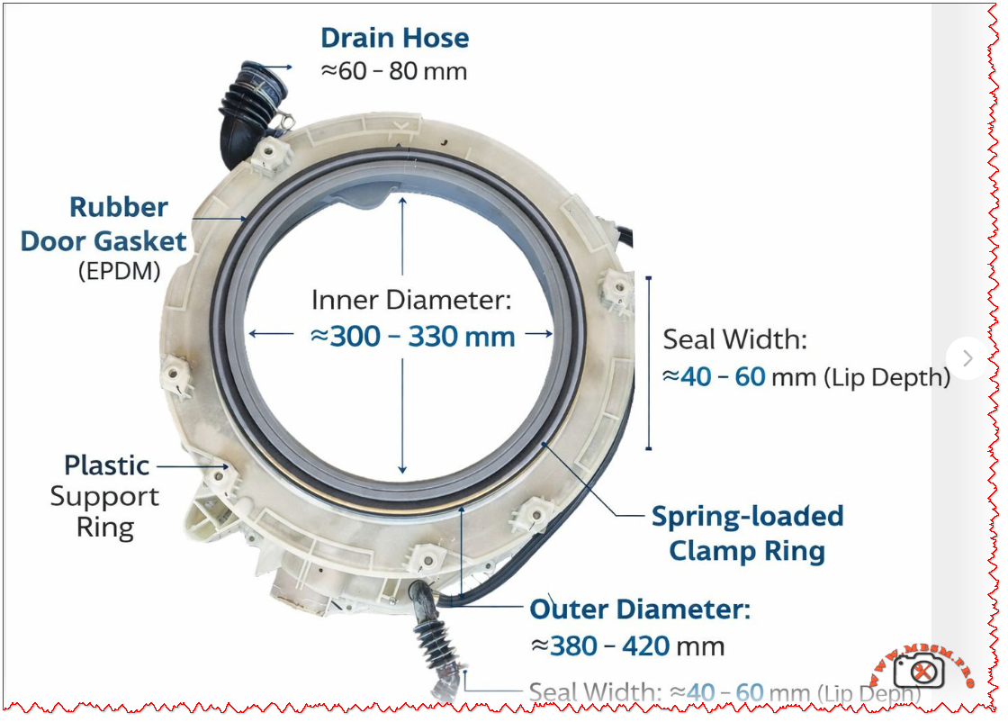
The tub front half assembly on Samsung front‑load washing machines combines the plastic support ring, EPDM rubber door gasket, drain hose and spring‑loaded clamp into one critical sealing unit between the drum and the cabinet front. It defines the loading opening (≈300–330 mm inner diameter) and overall front tub size (≈380–420 mm outer diameter), while controlling water drainage and leak‑free operation during high‑speed spin cycles.


Main components

  • Plastic support ring (semi tub front)
    The plastic semi tub front forms the rigid structure of the assembly and bolts to the rear half of the outer tub, typically listed in Samsung parts lists as “ASSY SEMI TUB FRONT”. It carries mounting points for the hinge area, latch, front panel screws and hose connections that surround the loading opening.
  • Rubber door gasket (EPDM)
    The grey EPDM door gasket works as a flexible diaphragm between the rotating stainless drum and the fixed plastic tub, absorbing vibration and preventing splashes through the door opening. Its lip depth or seal width is typically about 40–60 mm, providing a deep channel that guides water back into the tub instead of toward the door glass.​
  • Spring‑loaded clamp rings
    Two metal clamps are usually used: an inner clamp secures the gasket to the plastic tub, and an outer spring clamp band fixes it to the cabinet front panel. The outer band relies on a strong tension spring so that the elastomer lip remains compressed even under drum imbalance and door vibration at high spin speeds.
  • Drain hose connection
    A molded drain hose stub integrated into the front tub section channels residual water away from the gasket area and lower sump, typically matching Samsung’s EPDM drain hoses specified in spare‑parts diagrams. Hose internal diameters in this class of machines are commonly within 60–80 mm at the large bellows connection shown in the image, ensuring rapid evacuation and reducing standing water that could cause odors.​

Key dimensions from the assembly

The illustration corresponds to a common size range used on 7–9 kg Samsung front‑loaders, and the measurements help technicians and spare‑parts sellers match non‑OEM or compatible tubs and door boots.

Parameter Typical range (mm) Technical role
Inner opening diameter ≈300–330 Defines usable drum access and must match door glass and hinge geometry.
Outer tub front diameter ≈380–420 Matches cabinet cut‑out and rear tub half for correct bolt alignment.
Seal width / lip depth ≈40–60 Controls how deeply the gasket overlaps the drum rim and door glass to avoid leaks.​​
Drain‑hose connector length ≈60–80 Provides sufficient fall for water to clear the boot and flow to the pump housing.

Such dimensional ranges also influence replacement choices when original part numbers are no longer available, allowing cross‑referencing by diameter and seal width.


Typical failure modes and maintenance

  • Leakage and gasket damage
    Front leaks usually come from cuts, hardening or mold damage on the EPDM gasket lip, especially around the lower section where coins or sharp objects scrape during spin. Early signs include water tracks on the front panel, standing water in the door boot and musty odors after a cycle.​
  • Clamp loosening or mis‑seating
    If the spring clamp is not seated evenly in its groove after service, the boot can pull away from the cabinet, producing intermittent leaks only on high‑load or high‑speed programs. Corroded or stretched bands should always be replaced with genuine door‑seal clamp kits to maintain uniform radial pressure.​
  • Blocked drain hose connection
    Lint, detergent residue and small objects can partially block the drain hose stub shown at the bottom of the assembly, increasing water retention inside the boot and generating mold growth. Routine cleaning of the filter housing and periodic inspection of the lower hose path reduces these problems and extends component life.​

Replacement and selection tips

  • Identifying the correct part
    The fastest method is to read the full model code from the washer rating label and search for the matching “ASSY SEMI TUB FRONT” or “door boot / diaphragm” in Samsung’s illustrated parts lists or reputable spare‑parts catalogues. Where the exact code is unavailable, technicians can use the inner and outer diameters plus seal width shown in the image to select compatible universal boots within the 300–330 mm and 380–420 mm ranges.
  • Installation considerations
    When replacing the tub front half or door boot, manufacturers recommend removing the front panel, control panel and door lock assembly and carefully transferring hoses and wiring harness clips to the new ring. The gasket must be aligned to witness marks on the tub, with the drain holes positioned at the lowest point and both inner and outer clamps tightened uniformly to prevent wrinkles.​
  • Professional vs DIY service
    Although many guides and videos demonstrate door‑boot replacement as a do‑it‑yourself repair, full tub front‑half replacement involves heavy lifting and more extensive disassembly and is better performed by experienced technicians or advanced DIY users with proper support stands. For machines still under manufacturer warranty or covered by extended service contracts, any tub replacement should follow Samsung’s official service procedures and part numbers to maintain coverage.


Finder 66.82.8.230.0000 Power Relay: Reliable 30A Solution for HVAC and Industrial Control

Finder 66.82.8.230.0000 Power Relay: Reliable 30A Solution for HVAC and Industrial Control

The Finder 66.82.8.230.0000 is a high‑power, flange‑mount relay designed for demanding switching tasks in HVAC, refrigeration and industrial control panels. With a 230 V AC coil and 30 A contact rating, it offers a compact but robust alternative to contactors in many applications.

Product overview

The Finder 66.82 series is a family of 30 A power relays with Faston terminals and reinforced insulation that comply with international safety standards for electrical equipment. The 66.82.8.230.0000 variant pictured is a DPDT (2 changeover contacts) relay with a 230 V AC coil, suitable for single‑phase loads up to 440 V AC.

Mounted on a panel via integrated flanges, this relay is widely used in OEM machines, control panels and HVAC units where reliable separation between the control circuit and the power circuit is essential. Its compact housing and Faston 6.3 × 0.8 mm connections make wiring quick and maintenance friendly for installers and service technicians.

Key electrical specifications

For designers and technicians, the most critical data are contact rating, coil voltage and insulation performance. The table below summarizes the main technical characteristics of the Finder 66.82.8.230.0000 as presented in distributors’ listings and the manufacturer’s catalog.

Specification Value Notes
Manufacturer / Series Finder 66.82 Power relays 30 A series.
Coil voltage 230 V AC Standard mains control voltage.
Contact configuration DPDT (2CO) Two changeover contacts.
Max. switching current 30 A Per contact set for AC loads.
Max. switching voltage 440 V AC For power applications.
Terminals Faston 6.3 × 0.8 mm For push‑on connectors.
Mounting Flange mount For panel or chassis mounting.
Insulation Reinforced between coil and contacts According to EN 60335‑1.

These values make the relay particularly suitable for switching compressors, fan motors, heating elements and resistive or slightly inductive loads in HVAC and refrigeration systems.

Typical applications in HVAC and industry

In real‑world installations, the Finder 66.82.8.230.0000 often replaces bulkier contactors in medium‑power circuits where panel space and cost must be optimized. Common uses include:

  • Switching single‑phase compressors in cold rooms, display cabinets and small chillers up to 30 A at 230–250 V AC.
  • Controlling electric heaters, defrost elements and fan banks in air‑handling units and rooftop HVAC packages.
  • Interfacing low‑power thermostats, PLC outputs or electronic boards with mains loads in industrial machinery and building automation.

Because it provides reinforced insulation between coil and contacts, the relay is suitable for applications governed by household and similar equipment standard EN 60335‑1, which is frequently referenced in HVAC and appliance design. This insulation level enhances safety where user‑accessible electronics coexist with high‑voltage power circuits.

Installation and safety guidelines

When integrating this relay into a control panel, technicians should follow the wiring diagrams supplied in the Finder datasheet and the equipment manufacturer’s instructions. Faston terminations must be fully mated with correctly sized push‑on connectors, and conductors should be chosen according to the 30 A rating and ambient temperature in the enclosure.

The relay must be mounted on a flat surface using the dedicated flanges, ensuring adequate clearance for cooling and respecting creepage distances to nearby live parts. As with all power components, switching capacity must be derated for highly inductive loads, frequent cycling or elevated temperatures, conditions that are common in heavy‑duty HVAC duty cycles.


CR20-06 A-F-A-E-HQQE

Mbsm-pro-private-media2025-12-22_192145-1024x626-1

The Grundfos CR20-06 A-F-A-E-HQQE is a vertical multistage centrifugal pump delivering 21 m³/h at 70.4 m head with a 7.5 kW IE3 motor, designed for demanding water boosting and industrial applications.​​
Its cast‑iron base, stainless‑steel internals and HQQE mechanical seal make it a durable, energy‑efficient solution for process water, HVAC, boiler feed and general pressure boosting systems.


Introduction

In modern industry and building services, stable water pressure is no longer a luxury but a basic requirement. The Grundfos CR20-06 A-F-A-E-HQQE has become one of the quiet workhorses in this field, combining compact vertical design with serious performance for installations where downtime is simply not an option.


Technical profile of the CR20-06

The pump in the photo is clearly identified on its nameplate as a Grundfos CR20-06 A-F-A-E-HQQE with a 7.50 kW motor operating at 50 Hz and about 2919 rpm.​
It delivers a nominal flow of 21 m³/h at a rated head of 70.4 m, with a maximum head up to 88.4 m and a maximum operating pressure of 16 bar at liquid temperatures up to 120 °C.

Main nameplate data

Item Value
Pump type CR20-06 A-F-A-E-HQQE
Rated power P2 7.5 kW
Frequency / speed 50 Hz / ≈2919 rpm
Rated flow Q 21 m³/h
Rated head H 70.4 m
Maximum head Hmax 88.4 m
Maximum pressure / temp. 16 bar / 120 °C
Shaft seal code HQQE (single mechanical seal)
Pump orientation Vertical, inline
Efficiency (pump) ≈75.6% (MEI ≥ 0.70)

​​

The pump uses a vertical, inline layout with suction and discharge on the same level (DN 50 flanged connections, PN 25 rating), simplifying installation in compact plant rooms and on rigid pipe manifolds.
Its IE3 motor (size 132SB) offers motor efficiencies above 90% at typical loads, helping operators reduce long‑term energy costs.


Construction, materials and seal

The CR20-06 belongs to the widely used CR multistage family, where several impellers are stacked in series to build pressure while maintaining moderate flow.
In this specific model, the base and pump head are in cast iron, while all wetted parts such as impellers and chambers are stainless steel AISI 304, providing a good balance between robustness and corrosion resistance for clean water duties.

The HQQE mechanical seal is a single cartridge seal with silicon carbide/silicon carbide faces, EPDM elastomers and a stainless‑steel spring, designed for long service life and easy replacement.
This configuration suits cold and hot water, mildly aggressive media used in HVAC and process plants, and reduces the risk of dry‑running damage during commissioning or transient operating conditions.


Typical applications and operating benefits

With its 21 m³/h at 70.4 m operating point, the CR20-06 is well suited to medium‑pressure boosting in commercial buildings, industrial wash and rinse systems, boiler feed for small to mid‑size boilers, and general process water circulation.
Installers appreciate the inline design, which often allows direct replacement of older horizontal pumps without major changes to the pipework, while plant operators value the quiet operation and low vibration levels of the multistage design.

From an energy perspective, the combination of high hydraulic efficiency and IE3 motor makes this model a strong candidate in projects where life‑cycle cost analysis is required or where regulations demand a minimum efficiency index (MEI ≥ 0.70).
Paired with an external frequency converter, the CR20-06 can be turned into a variable‑speed booster, maintaining constant pressure in domestic water systems, process loops or district cooling circuits while cutting energy consumption during partial‑load operation.


Practical selection notes for engineers

When selecting a CR20-06 for a project, engineers typically start from the required duty point on the pump curve and verify that 21 m³/h at around 70 m head fits the system’s pressure losses, static height and safety margin.
System designers also check NPSH requirements, temperature range from −20 to 120 °C, and maximum ambient temperature up to 60 °C to ensure trouble‑free operation in machinery rooms and outdoor installations.

Because the pump offers a maximum operating pressure of 16 bar with PN 25 flanges, it can be integrated into higher‑pressure manifolds and ring mains, provided that upstream valves, fittings and vessels share compatible ratings.
For users planning future upgrades, the CR range gives a modular platform: additional models and variants can be combined in parallel booster sets, or replaced one‑to‑one if system demand increases.