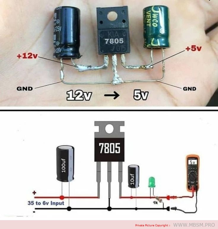
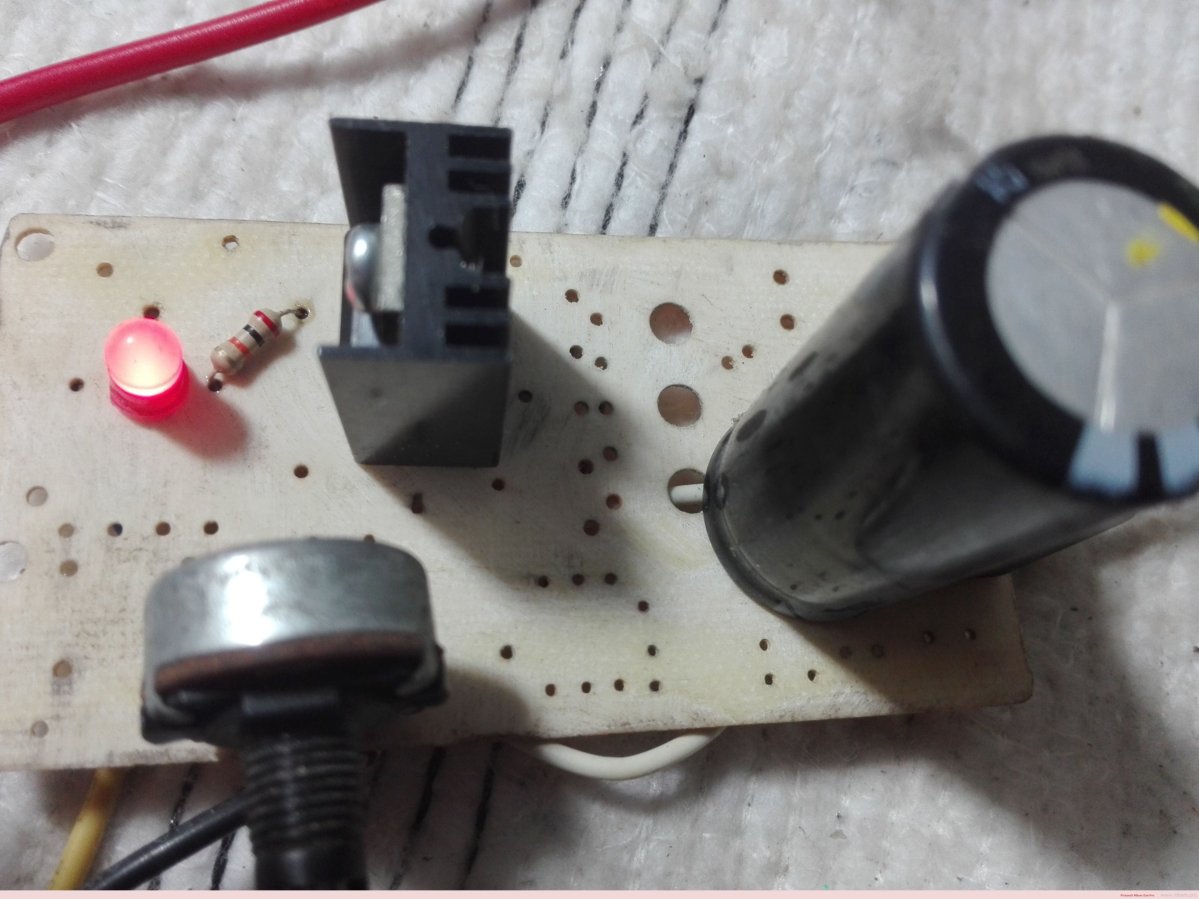
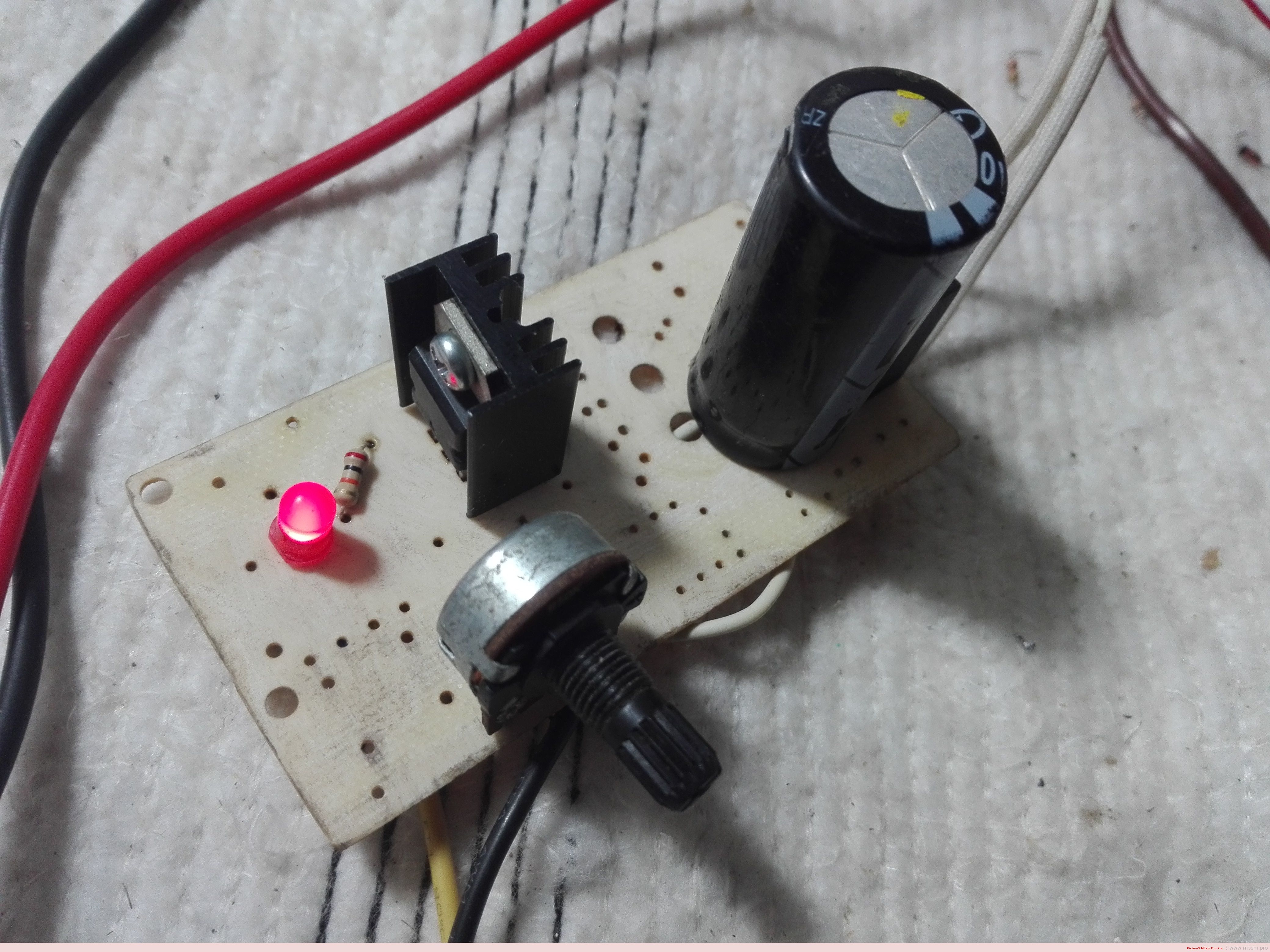
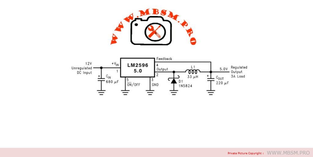
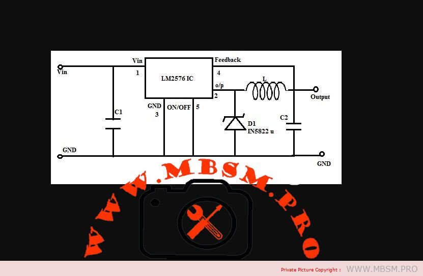
Mbsm.pro, 3A Adjustable voltage regulator circuit from 12 v to 5 v DC
Category: electronique
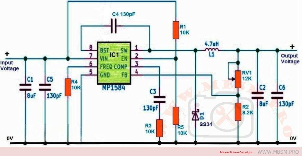
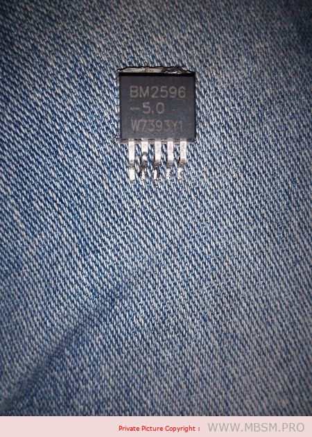
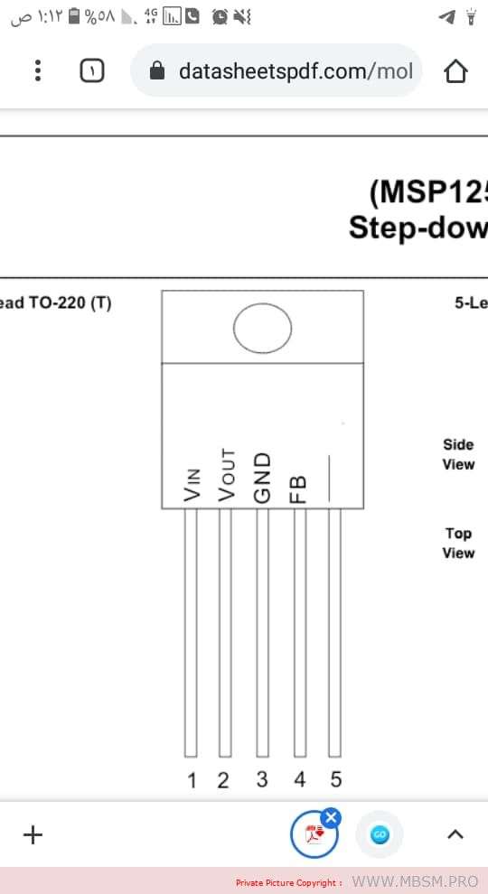
1. Switching Regulator with Adjustable Output:
- High Efficiency: Ideal for high-current applications due to their efficient power conversion, reducing heat generation.
- Wide Input Voltage Range: Often handle a broad range of input voltages.
- Compact Size: Typically smaller than linear regulators with similar current ratings.
- Adjustability: Some switching regulator ICs offer built-in adjustable output voltage control.
Examples of Switching Regulator ICs with Adjustable Output:
LM2596
LM2576
MP1584
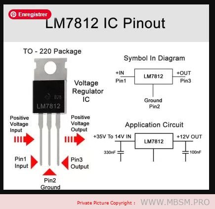
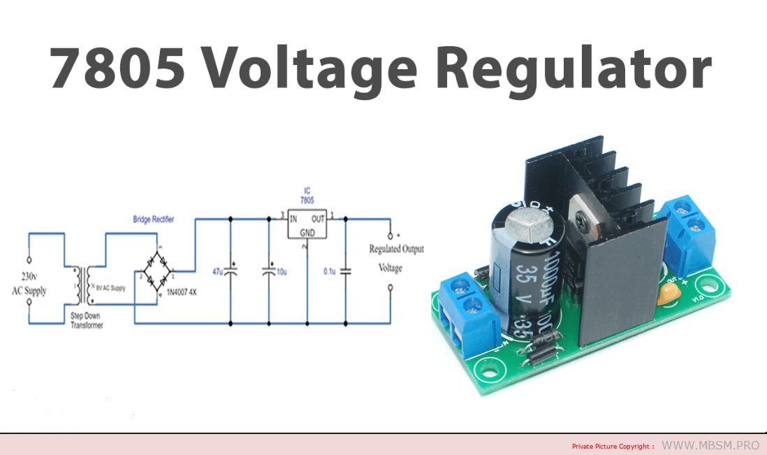
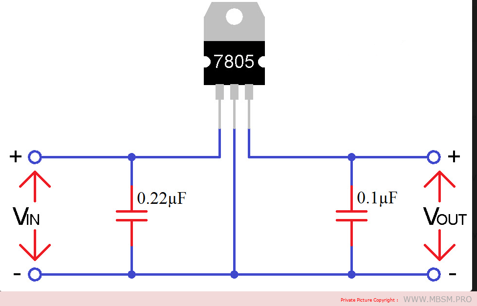
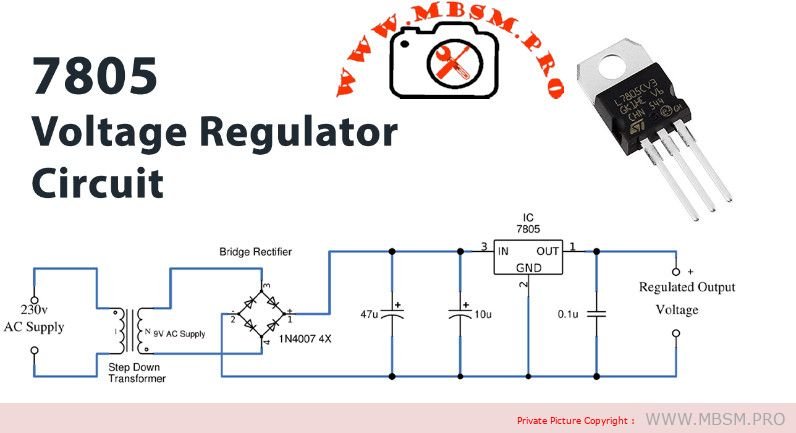
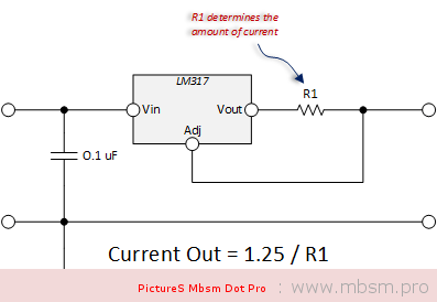
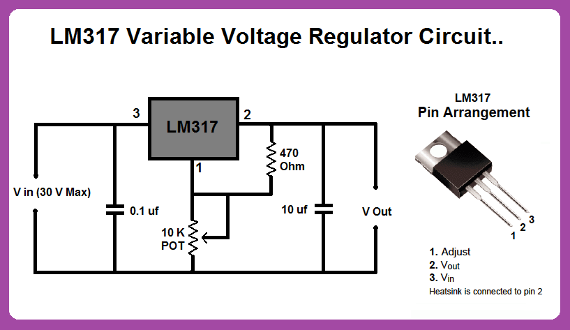
2. Linear Regulator with External Pass Transistor and Adjustable Control:
- Simpler Design: Uses a linear regulator IC, an external power transistor, and adjustable control components.
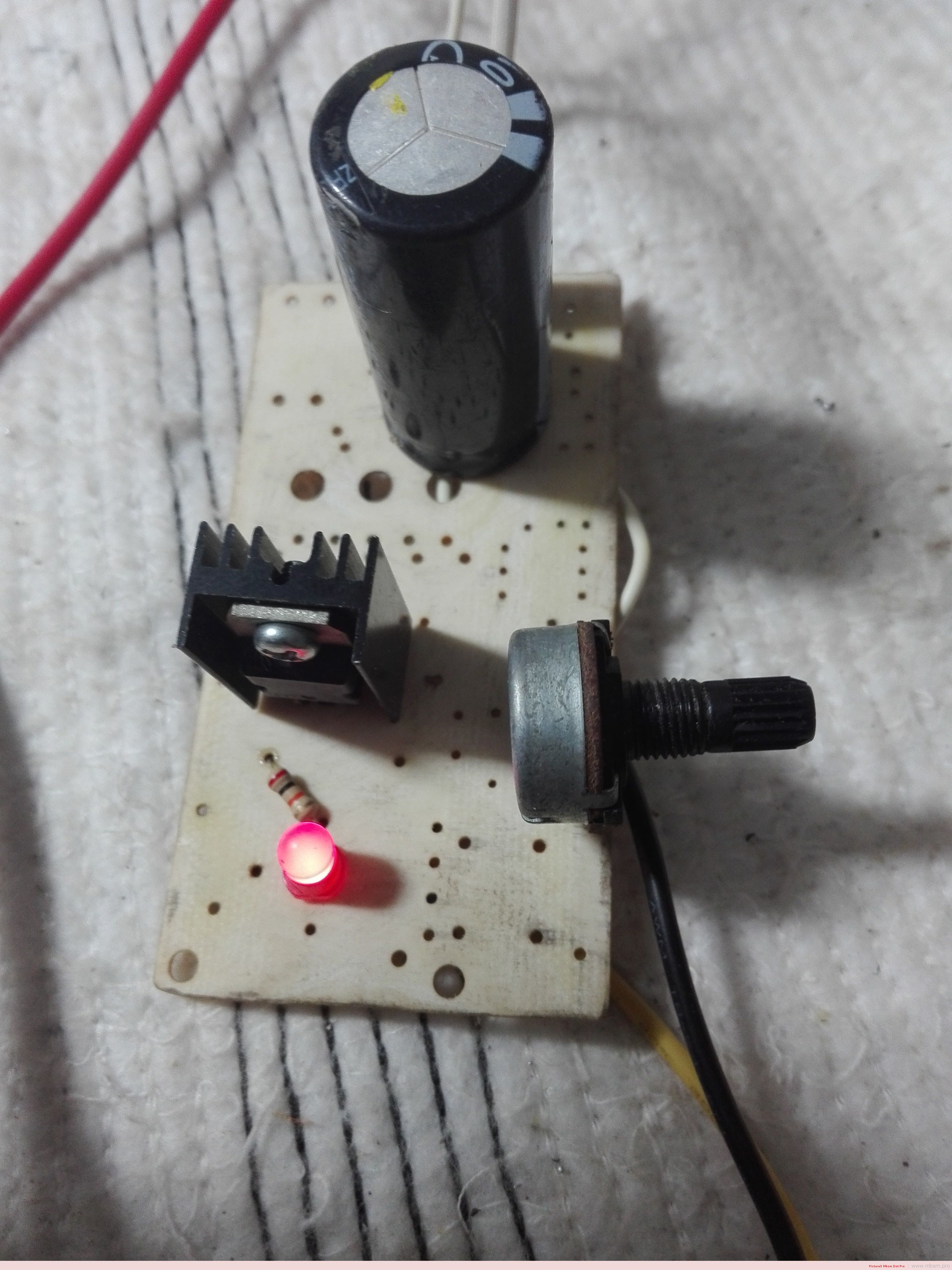
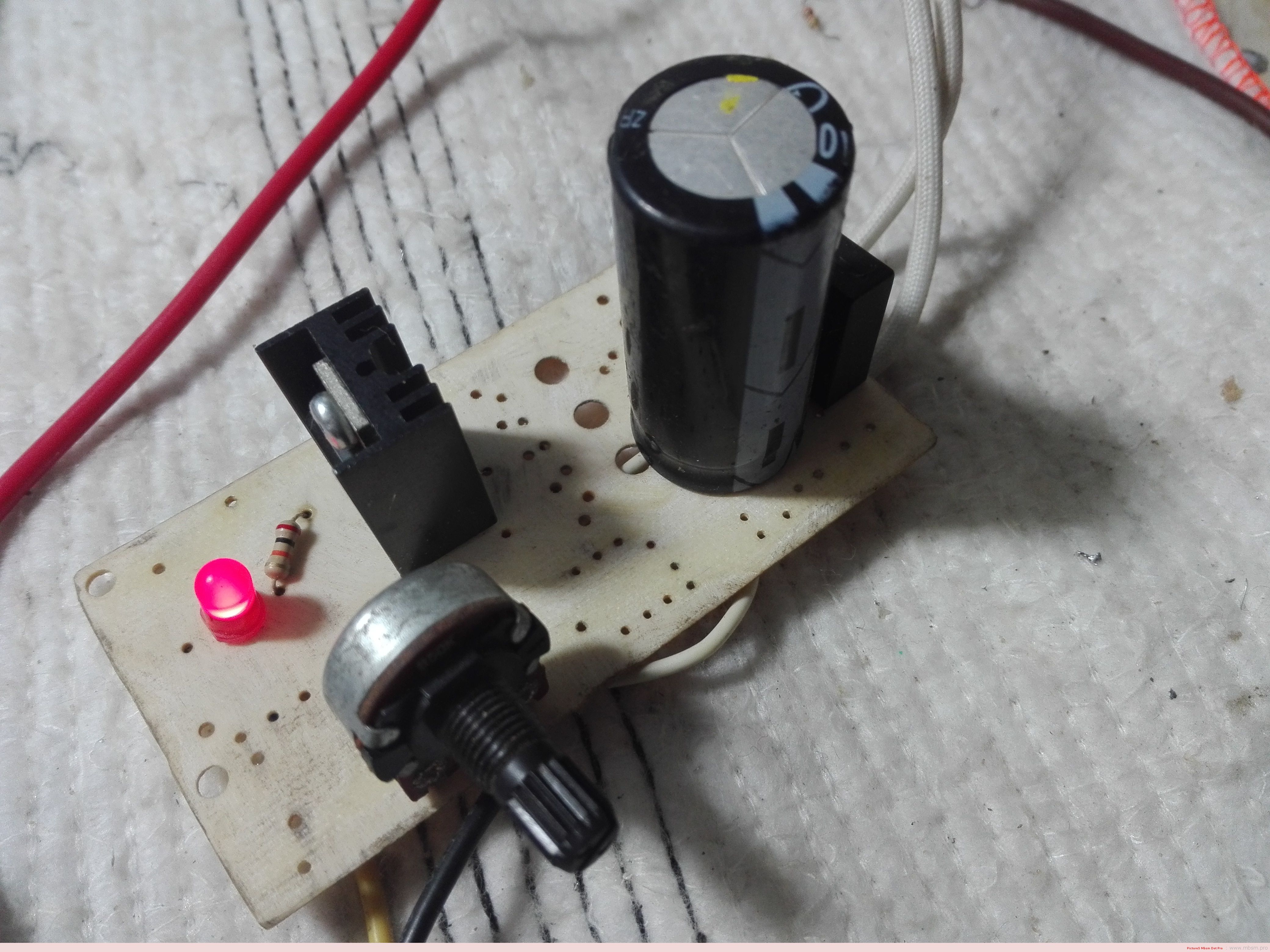
- Less Efficient: Dissipates excess power as heat, requiring adequate heatsinking.
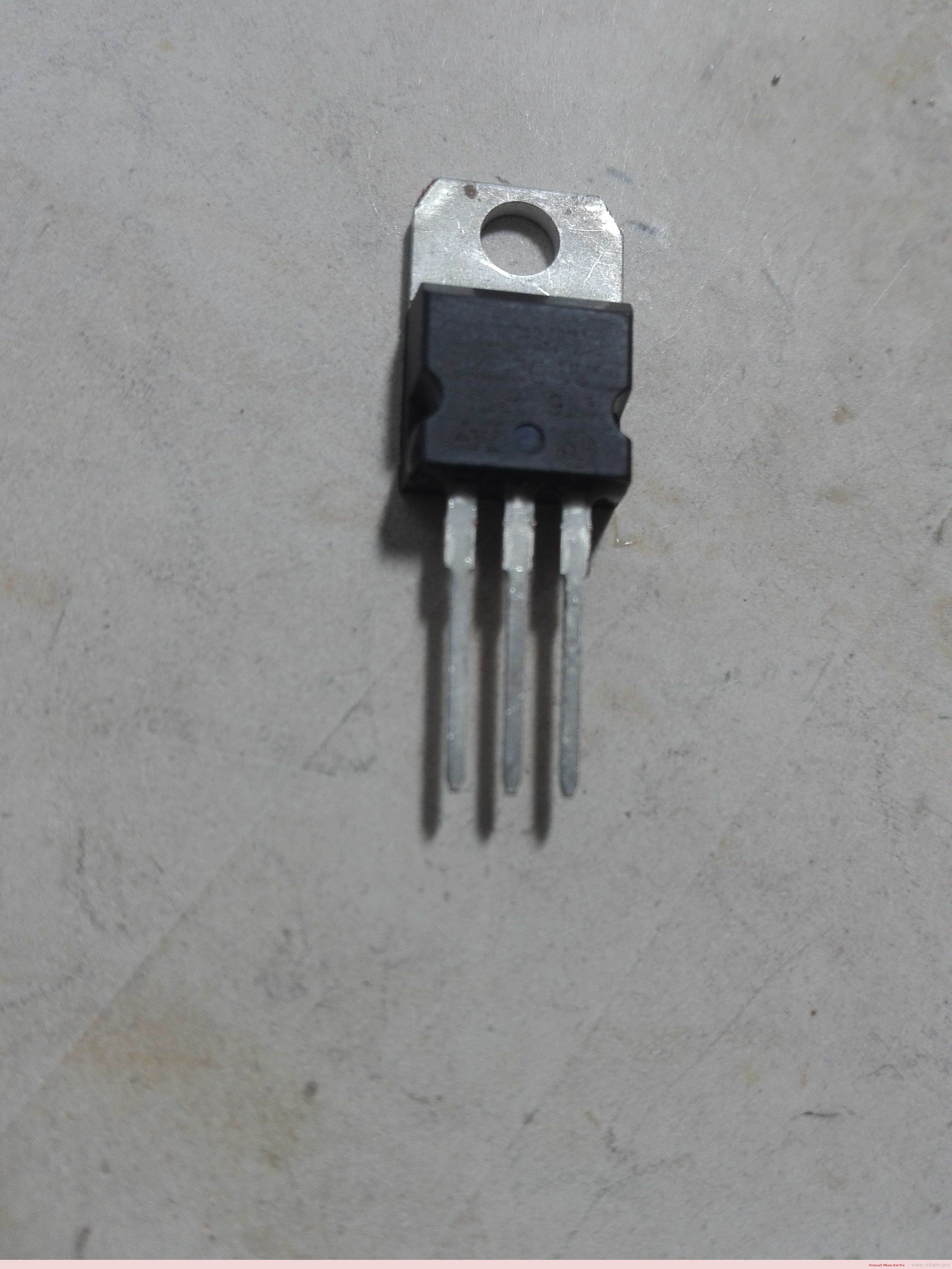
Components:
- Linear Regulator IC: Provides basic voltage regulation, but with a limited current output.
- Power Transistor: Handles high current flow.
- Heatsink: Dissipates heat from the transistor.
- Adjustable Resistors: Allow for fine-tuning of the output voltage.
Additional Considerations:
- Heat Dissipation: Both switching and linear regulators with high currents generate heat. Provide sufficient heatsinking.
- Input Voltage Range: Ensure the regulator can handle your input voltage range.
- Desired Adjustment Range: Choose a regulator that offers the level of output voltage adjustability you need.
- Safety Features: Consider regulators with overcurrent protection, thermal protection, and short-circuit protection.
Specific Circuit Design and Component Selection:
- Depend on your exact current, voltage, and adjustability requirements.
- Consult datasheets and application notes for the chosen regulator ICs for detailed guidance.